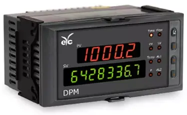
eyc-tech DPM05 Flow Computer
Specifications
- Product: eyc-tech DPM05 Flow Computer
- Function: Signal/Meter Flow Computer
- Features: Automatic calculation and cumulation of mass flow, standard volumetric flow, display of instantaneous flow and cumulative flow.
- Display: Digital display window with 5 digits
- Inputs: Flow, pressure compensation, temperature
- compensation
Function
The eyc-tech DPM05 Flow Computer is designed for automatic calculation and cumulation of mass flow and standard volumetric flow. It can simultaneously display measured values of instantaneous flow and cumulative flow. The unit of cumulative flow can be set without limitation. Users can switch between various display parameters such as instantaneous flow, time, current cumulative flow, total cumulative flow, input values for flow, pressure compensation, and temperature compensation.
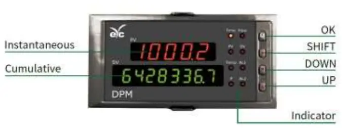
Display Panel and Function Keys
The device features a digital display window with 5 digits forPV display. Function keys include OK key for confirmation, Page Down key for parameter settings, Setting exit key for return ng to the measurement screen, and keys for adjusting decimal point position.
Power-on Setting
Upon powering on, the flow computer enters self-test status andtransitions to working status upon completion. Users can navigate through various menus and settings using specific key combinat ions mentioned in the manual.
Parameters Setting
In the working status, users can access Level 1 parameters setting by following the instructions provided in the manual.
FAQs
Q: How do I reset the device to factory default settings?
A: If Loc = 577, in the Loc menu, press specific keys simultaneously to restore all parameters to factory default settings.
Q: How can I return to real-time measurement status fromparameter setting?
A: You can either manually press specific keys or wait for the device to automatically return to real-time measurement status after a certain period.
Flow computer
Flow computer Operation Instruction
I. Function Automatic calculation and cumulation of mass flow; Automatic calculation and cumulation of standard volumetric flow; Simultaneous display of measured values of instantaneous flow and cumulative flow (unit of
cumulative flow may be set without limitation); Switch between display of measured value of instantaneous flow, time, current cumulative flow,
total cumulative flow of 11-digit, flow (differential pressure, frequency) input, pressure compensation input value, temperature compensation input value;
Small signals cut-off function (display “0” when instantaneous flow is less than set value) available; Quantitative control of flow available; Automatic temperature and pressure compensation available; The following sensors may be chosen through programming: 1. P: differential pressure type flow sensor input; 2. P, T: differential pressure type flow sensor and temperature sensor input; 3. P, P, T: differential pressure type flow sensor, pressure sensor and temperature sensor input; 4. f: frequency type flow sensor input; 5. f, T: frequency type flow sensor and temperature sensor input; 6. f, P: frequency type flow sensor and temperature sensor input; 7. f, P, T: frequency type flow sensor, pressure sensor and temperature sensor input; 8. G: flow sensor (linear flow signals) input; 9. G, T: flow sensor and temperature sensor input; 10. G, P: flow sensor and pressure sensor input; 11. G, T, P: flow sensor, temperature sensor and pressure sensor input
Three kinds of compensation are available: Automatic temperature compensation; Automatic pressure compensation; Automatic temperature and pressure compensation Display function: Display of measured value of instantaneous flow, current cumulative flow, measured value of differential pressure, measured value of pressure compensation, measured value of temperature compensation and frequency etc of each channel; PV + SV display of cumulative flow: 11 digits (0 ~ 99999999.999) Display of current date and time Storage of total cumulative flow under power failure; automatic clear of total cumulative flow when it reaches full range (99999999.999); current cumulative flow will not be stored under power failure.
II. Display Panel and Function Keys
1
Signal / Meter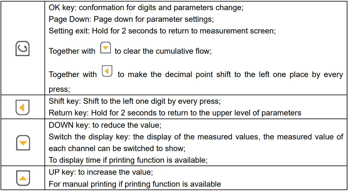
Flow computer
1) Digital display window: PV display window (5 digits): Display of instantaneous flow; in the parameters setting status, display of parameter symbols;
input of flow compensation, pressure compensation, and temperature compensation may also be displayed through proper setting;
SV display window (8 digits): Display of cumulative flow; in the parameters setting status, display of set value; PV + SV display window (totally 11 digits): internal parameters may be set to display total cumulative value of 11 digits (millions digit is the third digit on the right of number displayed on PV window). 2) Panel indicators AL1: Alarm 1 indicator AL2: Alarm 2 indicator t—-Time: Current time indicator q—-flow-rate: instantaneous flow indicator T—-Temperature: temperature compensation indicator P—-Pressure : pressure compensation indicator F—-Flow: differential pressure and flow indicator Sum: current cumulative value indicator 3) Operation button
OK key: conformation for digits and parameters change; Page Down: Page down for parameter settings; Setting exit: Hold for 2 seconds to return to measurement screen;
Together with to clear the cumulative flow;
Together with
to make the decimal point shift to the left one place by every
press; Shift key: Shift to the left one digit by every press; Return key: Hold for 2 seconds to return to the upper level of parameters DOWN key: to reduce the value; Switch the display key: the display of the measured values, the measured value of each channel can be switched to show; To display time if printing function is available; UP key: to increase the value; For manual printing if printing function is available 4) Instrument wiring Attention shall be paid to the following items during wiring: PV input (process input) 1. To reduce electrical interference, the low-voltage DC signal and sensor input wire should stay away from heavy-current electrical wire. Otherwise, shielded wire shall be used and grounding shall be made at the same point. 2. Any device between the sensor and terminal may affect the measurement accuracy due to resistance or leakage current. Thermocouple or pyrometer input Compensation wires corresponding to the thermocouple shall be used as extension wire, which
2
Signal / Meter
Flow computer
shall be shielded as far as possible. RTD (platinum resistance) input The resistance for 3 wires must be the same, which shall not exceed 15.
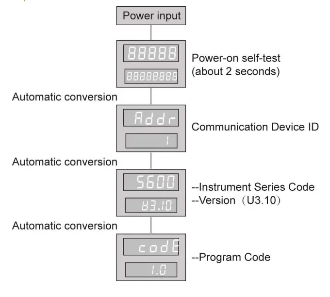
III. Power-on Setting As soon as the instrument is powered on, it enters into the self-test status (see figure in the right),
and when self-test is completed, it automatically enters into the working status. In the working status,
press
and it displays LOC. LOC parameters could be set as follows:
1.1) You can enter into Level 1 menu whatever the Loc is (no locking if LOC=00, 132);
2) When Loc = 132, press
for 4 seconds to enter into Level 2 menu;
3) When Loc = 128, press calculation of flow coefficient;
for 4 seconds to enter into Level 3 menu for automatic
4) When Loc = 130, press
for 4 seconds to enter into the time setting menu;
5) When Loc = 111, While pressing the key value manually cleared
and the key
to allow this accumulated flow
6) When Loc = 112, While pressing the key
and the key
the total accumulated flow values manually cleared;
to allow this accumulation and
7) When Loc = other values, pressure
for 4 seconds to return to the measuring screen.
2. If Loc = 577, in the Loc menu, press the parameters to factory default settings.
and for 4 seconds simultaneously to restore all
3. In any other menu, pressure Back to working status
for 4 seconds to return to the measuring screen.
1. Manual: In the status of parameters setting, press
for 4 seconds, the instrument will
automatically return to real-time measurement status. 2. Auto: In the status of parameters setting, do not press any key. After 30 seconds the instrument
will automatically return to real-time measurement status.
3
Signal / Meter Flow computer
4
IV. Parameters Setting 4.1 Level 1 parameters setting
In the working status, press
Signal / Meter Flow computer
and PV will display LOC and SV display the parameter values:
press or to set parameters. Press
for 2 seconds to return to upper level of parameters.
You can enter into Level 1 parameter setting by pressing
when Loc = any value.
Default setting
Parameters
Parameters locking
Alarm 1 set value Alarm 2 set value
Setting Range
0 ~ 999
-199999 ~ 999999
-199999 ~ 999999
Description LOC=00: No locking (Level 1 parameters can be modified) LOC00, 132: Locking (Level 1 parameters can not be modified) LOC=132: No locking (Level 1 and Level 2 parameters can be modified)
Set value of Alarm 1
Set value of Alarm 2
Alarm 1 return difference
0 ~ 999999 Return difference value of Alarm 1
Alarm 2 return difference
Flow coefficient 1 Flow coefficient 2 Flow coefficient 3 Flow coefficient 4
0 ~ 999999 Return difference value of Alarm 2
0 ~ 999999 0 ~ 999999 0 ~ 999999 0 ~ 999999
Display flow coefficient of differential pressure type flow sensor, frequency type flow sensor, and pressure sensor input See the figure of flow compensation coefficient Kx. Display flow coefficient of differential pressure type flow sensor, frequency type flow sensor, and pressure sensor input See the diagram of flow compensation coefficient Kx. Display flow coefficient of differential pressure type flow sensor, frequency type flow sensor, and pressure sensor input See the diagram of flow compensation coefficient Kx. Display flow coefficient of differential pressure type flow sensor, frequency type flow sensor, and pressure sensor input See the diagram of flow compensation coefficient Kx.
Density compensation
constant
0 ~ 999999
Display the density compensation constant of measured medium
Density compensation
coefficient
0 ~ 999999
Display the density compensation coefficient of measured medium
Density in operating condition
0 ~ 999999
Display the density of measured medium in operating condition (unit: Kg/m3)
Density in standard condition
0 ~ 999999
Display the density of measured medium in standard condition (1 bar, 20 ) ( unit: Kg/m3)
5
Signal / Meter Flow computer
Default setting
Parameters
Setting Range
Description
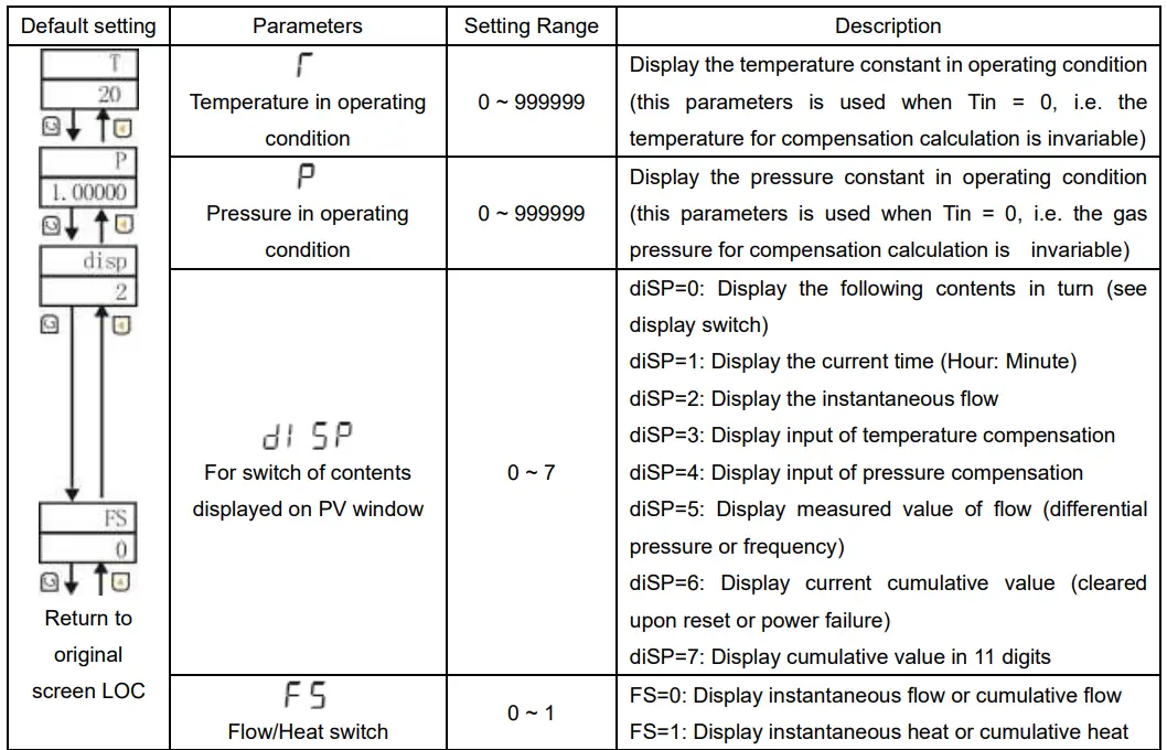
Display the temperature constant in operating condition
Temperature in operating 0 ~ 999999 (this parameters is used when Tin = 0, i.e. the
condition
temperature for compensation calculation is invariable)
Display the pressure constant in operating condition
Pressure in operating
0 ~ 999999 (this parameters is used when Tin = 0, i.e. the gas
condition
pressure for compensation calculation is invariable)
diSP=0: Display the following contents in turn (see
display switch)
diSP=1: Display the current time (Hour: Minute)
diSP=2: Display the instantaneous flow
diSP=3: Display input of temperature compensation
For switch of contents
0 ~ 7
diSP=4: Display input of pressure compensation
displayed on PV window
diSP=5: Display measured value of flow (differential
pressure or frequency)
diSP=6: Display current cumulative value (cleared
Return to
upon reset or power failure)
original
diSP=7: Display cumulative value in 11 digits
screen LOC
Flow/Heat switch
0 ~ 1
FS=0: Display instantaneous flow or cumulative flow FS=1: Display instantaneous heat or cumulative heat
Notes on flow compensation coefficient Kx:
When Level 2 parameter KE = 1, nonlinear compensation of flow input can be achieved through
Level 1 parameter Kx. The figure of compensation coefficient K is as follows:
Nonlinear input signal of flow can be compensated through setting coefficient Kx; This function can be also used for small signal cut-off of frequency input; Flow rate (linear, differential or frequency) of the input value is less than 1/3, the coefficient K1 for compensation; flow rate (linear, differential or frequency) of the input value is greater than the FH by K4 as coefficient compensation. For linear compensation, Level 2 parameter KE will be generally set to be 0, so only parameter K1 will be served as compensation coefficient in Level 1 parameter setting, and K2, K3, K4 will not be displayed. Note: this function is invalid in the case of frequency input, in which case error will occur to the program if this parameter has been set. Control output type (AL1, AL2, AH1, AH2)
6
Signal / Meter
Flow computer
Control output type can be set by Level 2 parameter “ALM”; see details below.
Symbol Name Setting Range Function description
Output type
– No alarm;
– Upper limit alarm of instantaneous flow;
– Lower limit alarm of instantaneous flow;
ALM1 Alarm 1
Full range
– Quantitative process output of flow: auto start, output “1”,
– Quantitative result output of flow: auto start, output “0”,
– Quantitative result output of flow: auto start, auto clear, impulse See details
width output
below
– No alarm;
– Upper limit alarm of instantaneous flow;
ALM2 Alarm 2 Full range – Lower limit alarm of instantaneous flow;
– Quantitative process output of flow: auto start, output “1”;
– Quantitative result output of flow: auto start, output “0” ;
(1) This instrument will have a return difference for alarm/control output to prevent frequent action
during fluctuation of output relay at output critical point; it works as followed:
The measured value increases from a low value:
The measured value decreases from a high value: Upper limit alarm output: Lower limit alarm output:
7
Signal / Meter Flow computer (2) Quantitative control output of flow 1.Sequence diagram of AL1 quantitative control output: AL1 quantitative process control output: (auto start, output “1”)
AL1 quantitative result control output: (auto start, output “0”)
AL1 quantitative result control output: (auto clear, impulse width output)
2. AL2 quantitative control output timing diagram AL2 quantitative process control output: (manual start, and outputs “1”)
AL2 quantitative control output: (manually start the output of “0”)
AH2 means control output lead value. Upon control output of the instrument, if there’s still instantaneous flow input, it will continue to be accumulated. Upon the control output, current control is completed. Manual start is required for next control upon which control output will continue. Method of starting quantitative control of flow in AL2 (AL2: manual start of quantitative control) 1. Press the external switch of “Start”, and it starts quantitative control of flow; 2. Set Level 1 parameter LOC as 111, and in the status where PV window displays measured value,
8
Signal / Meter Flow computer
press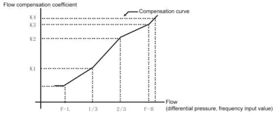
to start quantitative control of flow.
Method of stopping quantitative control of flow in AL2 (AL2: manual start of quantitative control): 1. Press the external switch of “Stop”, and it stops quantitative control output of flow; 2. Set Level 1 parameter LOC as 111, and in the status where PV window displays measured value,
press
and simultaneously to stop quantitative control output of flow.
When key “Stop” is pressed, control output will be stopped no matter whether there’s quantitative control output; if there’s still instantaneous flow input at this time, it will be accumulated. In order to initiate quantitative control output of cumulative flow, quantitative control output of flow must be “started” again.
Current cumulative value will be cleared in case of power failure or reset. Press
and
simultaneously for manual clear of value. In case of quantitative control with external switch, press external switch “Clear” for manual clear of value.
The total cumulative value will be cleared when it reaches full 11 digits. In case of need for clear before it reaches full 11 digits, set Level 1 parameter LOC as 111, and in the status where PV window
displays measured value, press
and
simultaneously for manual clear. In case of quantitative
control with external switch, press external switch “Clear” for manual clear of value. The maximum cumulative flow of the instrument is 99999999999, and Level 2 parameters can
be set to change display form within the range of 99999999.999 to 999999999.99. 4.2 Level 2 parameters setting
In the working status, press
and PV will display LOC and SV display parameter values; press
or
for setting. Press and hold the key
for 2 seconds to return back to the upper level
parameters; when Loc = 132, press
for 4 seconds to enter into Level 2 parameters setting.
9
Signal / Meter Flow computer
Default setting
Parameters
Setting range
Description
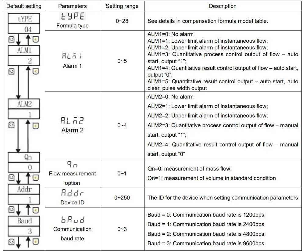
Formula type Alarm 1
Alarm 2
0~28 0~5
0~4
See details in compensation formula model table.
ALM1=0: No alarm ALM1=1: Lower limit alarm of instantaneous flow; ALM1=2: Upper limit alarm of instantaneous flow; ALM1=3: Quantitative process control output of flow auto start, output “1”; ALM1=4: Quantitative result control output of flow auto start, output “0”; ALM1=5: Quantitative result control output auto start, auto clear, pulse width output ALM2=0: No alarm
ALM2=1: Lower limit alarm of instantaneous flow;
ALM2=2: Upper limit alarm of instantaneous flow;
ALM2=3: Quantitative process control output of flow manual
start, output “1”;
ALM2=4: Quantitative result control output of flow manual
start, output “0”
Qn=0: measurement of mass flow;
Flow measurement
0~1
Qn=1: measurement of volume in standard condition
option
Device ID
Communication baud rate
0~250 0~3
The ID for the device when setting communication parameters
Baud = 0: Communication baud rate is 1200bps; Baud = 1: Communication baud rate is 2400bps Baud = 2: Communication baud rate is 4800bps; Baud = 3: Communication baud rate is 9600bps
10
Signal / Meter Flow computer
Default setting
Parameters
Setting range
Description
Time unit of instantaneous flow
display
Precision of cumulative flow
display
Decimal point of instantaneous flow
display
Time unit of instantaneous heat
display
Precision of cumulative heat
display
Decimal point of instantaneous heat
display
Q-Tn=0: second ;
Q-Tn=1: minute;
0~5
Q-Tn=2: hour;
Q-Tn=3: 1/10 hour;
Q-Tn=4: 1/100 hour;
Q-Tn=5: 1/1000 hour
M-dP=0: 1 (displayed as XXXXXX); M-dP=1: 0.1 (displayed as XXXXX.X); 0~3 M-dP=2: 0.01 (displayed as XXXX.XX); M-dP=3: 0.001 (displayed as XXX.XXX) Q-dP =0: no decimal point (displayed as XXXX); Q-dP =1: Ten decimal places (displayed as XXX.X) 0~3 Q-dP=2: One hundred decimal places (displayed as XX.XX) Q-dP=3: One thousand decimal places (displayed as X.XXX) H-Tn=0: second ; H-Tn=1: minute; H-Tn=2: hour; 0~5 H-Tn=3: 1/10 hour; H-Tn=4: 1/100 hour; H-Tn=5: 1/1 000 hour N-dP=0: 1 (displayed as XXXXXX); N-dP=1: 0.1 (displayed as XXXXX.X); 0~3 N-dP=2: 0.01 (displayed as XXXX.XX); N-dP=3: 0.001 (displayed as XXX.XXX) H-dP=0: no decimal point (displayed as XXXX); H-dP =1: Ten decimal places (displayed as XXX.X) 0~3 H-dP=2: One hundred decimal places (displayed as XX.XX) H-dP=3: One thousand decimal places (displayed as X.XXX)
Decimal point of temperature compensation display
T-dP=0: no decimal point (displayed as XXXX); T-dP =1: Ten decimal places (displayed as XXX.X) 0~3 T-dP =2: One hundred decimal places (displayed as XX.XX) T-dP=3: One thousand decimal places (displayed as X.XXX)
Decimal point of pressure
compensation display
P-dP=0: no decimal point (displayed as XXXX); P-dP =1: Ten decimal places (displayed as XXX.X) 0~3 P-dP=2: One hundred decimal places (displayed as XX.XX) P-dP=3: One thousand decimal places (displayed as X.XXX)
Decimal point of flow (linear differential
pressure) display
F-dP=0: no decimal point (displayed as XXXX); F-dP =1: Ten decimal places (displayed as XXX.X) 0~3 F-dP=2: One hundred decimal places (displayed as XX.XX) F-dP=3: One thousand decimal places (displayed as X.XXX)
Filter coefficient of instantaneous flow
0~19
Filter coefficient of instantaneous flow 11
Signal / Meter Flow computer
Default setting
Parameters
Setting range
Description
Type of temperature compensation input
0~35
See Graduation Table in Model Selection section.
Type of pressure compensation input
25~35
See Graduation Table in Model Selection section.
Type of flow input (linear, differential pressure type)
Zero shift of temperature compensation
25~36
See Graduation Table in Model Selection section.
Full range
Set the zero shift for display of measured value of temperature compensation (see Note 1)
Amplification scale of measuring range of temperature compensation
Zero shift of pressure compensation
0~1.999
Set the amplification scale of measuring range for display of temperature compensation (see Note 1)
Full range
Set the zero shift for display of measured value of pressure compensation (see Note 1)
Amplification scale of measuring range of pressure
compensation
Zero shift of flow input
0~1.999 Full range
Set the amplification scale of measuring range for display of pressure compensation (see Note 1)
Set the zero shift for display of measured value of flow input (see Note 1)
Amplification scale of measuring range of flow
input
Zero shift of transmission output 1
Amplification scale of transmission output 1
Zero shift of transmission output 2
Amplification scale of transmission output 2
Lower limit of measuring range of transmission output
0~1.999 0~1.200 0~1.900 0~1.200 0~1.900 0~999999
12
Set the amplification scale of measuring range for display of flow input (see Note 1)
Set the zero shift for display of transmission output 1 (see Note 2)
Set the amplification scale for display of transmission output 1 (see Note 2)
Set the zero shift for display of transmission output 2 (see Note 2)
Set the amplification scale for display of transmission output 2 (see Note 2) Set the lower limit of measuring range of transmission output, which shall be subject to the instantaneous flow.
Signal / Meter Flow computer
Default setting
Parameters
Upper limit of measuring range of transmission output
Atmospheric pressure in operating condition
Lower limit of measuring range of temperature compensation
Upper limit of measuring range of temperature compensation
Lower limit of measuring range of pressure compensation
Upper limit of measuring range of pressure compensation
Lower limit of measuring range of flow input
Upper limit of measuring range of flow input
Setting range 0~999999 Full range Full range Full range Full range
Full range Full range Full range
Description Set the lower limit of measuring range of transmission output, which shall be subject to the instantaneous flow. Set the atmospheric pressure at the site where the instrument operates. Unit: depending on set value of P-u; common units: MPa, KPa, Kgf/cm2, bar and etc. Standard unit: MPa Set the lower limit of measuring range of temperature compensation Unit: Set the upper limit of measuring range of temperature compensation Unit: Set the lower limit of measuring range of pressure compensation Unit: depending on set value of P-u; common units: MPa, KPa, Kgf/cm2, bar and etc. Standard unit: MPa Set the upper limit of measuring range of pressure compensation Unit: depending on set value of P-u; common units: MPa, KPa, Kgf/cm2, bar and etc. Standard unit: MPa Set the lower limit of measuring range of flow input Unit: same as output signal of flow meter; MPa in the case of differential pressure input Set the upper limit of measuring range of flow input Unit: same as output signal of flow meter; MPa in the case of differential pressure input
Small signal cutoff of flow input
Full range
Set small signal cutoff of flow input
Unit of temperature compensation
Unit of pressure compensation Unit of flow input
Unit of instantaneous flow Unit of instantaneous heat
0 ~ 45
0 ~ 45 0 ~ 45 0 ~ 45 0 ~ 45
13
See Unit Code Table See Unit Code Table See Unit Code Table See Unit Code Table See Unit Code Table
Signal / Meter Flow computer
Default setting
Return to original screen tyPE
Parameters Alarm printing Interval of printing
Mode of flow coefficient compensation
Temperature input Pressure input
Setting range 0 ~ 1
Description Pr-A = 0: no alarm printing function Pr-A = 1: alarm printing function available
1 ~ 2400 minutes Set the interval of timed printing
0 ~ 1
0 ~ 1 0 ~ 1
KE=0: flow coefficient K linear compensation (only Level 1 parameter K1 used for compensation ) KE=1: flow coefficient K nonlinear compensation (Level 1 parameters K1, K2, K3, K4 used for compensation) Tin=0: Temperature as a constant Tin=1: Temperature input from external sensor Tin=0: Pressure as a constant Tin=1: Pressure input from external sensor
Compensation formula model table:
Code
Compensation type
0
Internal reserved parameter
1
Superheated steam (temperature / pressure compensation)
2
Saturated steam (temperature compensation)
3
Saturated steam (pressure compensation)
4
General medium (temperature / pressure compensation)
5
General medium (temperature compensation)
6
General medium (pressure compensation)
7
General medium (no compensation)
8
Superheated steam (temperature / pressure compensation)
9
Saturated steam (temperature compensation)
10 Saturated steam (pressure compensation)
11 General medium (temperature / pressure compensation)
12 General medium (temperature compensation)
13 General medium (pressure compensation)
14 General medium (no compensation)
15 Superheated steam (temperature / pressure compensation)
16 Saturated steam (temperature compensation)
17 Saturated steam (pressure compensation)
18 General medium (temperature / pressure compensation)
19 General medium (temperature compensation)
20 General medium (pressure compensation)
21 General medium (no compensation)
22 Superheated steam (temperature / pressure compensation)
23 Saturated steam (temperature compensation)
14
Note Reserved parameter
Linear input Linear input Linear input Linear input Linear input Linear input Linear input Non-extracted signal Non-extracted signal Non-extracted signal Non-extracted signal Non-extracted signal Non-extracted signal Non-extracted signal Extracted signal Extracted signal Extracted signal Extracted signal Extracted signal Extracted signal Extracted signal Frequency input Frequency input
Signal / Meter
Flow computer
24 Saturated steam (pressure compensation)
Frequency input
25 General medium (temperature / pressure compensation)
Frequency input
26 General medium (temperature compensation)
Frequency input
27 General medium (pressure compensation)
Frequency input
28 General medium (no compensation)
Input signal types table:
Frequency input
Degree no .Pn
Signal types
measuring range Degree no Pn
Signal types
measuring range
0
Thermocouple B
4001800
18
Remote Resistance -19999999
0350
1
Thermocouple S
01600
2
Thermocouple K
01300
19
Remote Resistance -19999999
3 0350
20
020mV
-19999999
3
Thermocouple E
01000
21
040mV
-19999999
4
Thermocouple T
-200.0400.0
22
0100mV
-19999999
5
Thermocouple J
01200
23
-2020mV
-19999999
6
Thermocouple R
01600
24
-100100mV -19999999
7
Thermocouple N
01300
25
020mA
-19999999
8
F2
7002000
26
010mA
-19999999
9
Thermocouple Wre3-25
02300
27
420mA
-19999999
10
Thermocouple Wre5-26
02300
28
05V
-19999999
11
RTD Cu50
-50.0150.0
29
15V
-19999999
12
RTD Cu53
-50.0150.0
30
-55V
-19999999
13
RTD Cu100
-50.0150.0
31
010V
-19999999
14
RTD Pt100
-200.0650.0
32
010mA square -19999999
15
RTD BA1
-200.0600.0
33
420mA square -19999999
16
RTD BA2
-200.0600.0
34
05V square
-19999999
17
Linear resistance 0
-19999999
400
35
-19999999
15V square
Unit code table:
Code
0
Unit
kgf
1
2
3
4
5
6
Pa KPa MPa mmHg mmH2O
bar
7
8
9
10 11
%
Hz
m
t
Code
12
13
14
15
16
17
18
19
20
21
22
23
Unit
l
m3
kg
J
MJ
GJ
Nm3
m/h
t/h
l/h m3/h Kg/h
Code
24
25
26
27
28
29
30
31
32
33
34
35
Unit
J/h MJ/h GJ/h Nm3/h m/m
t/m
l/m
m3/m Kg/m J/m MJ/M GJ/m
Code
36
37
38
39
40
41
42
43
44
45
Unit Nm3/m m/s
t/s
l/s
m3/s
Kg/s
J/s
MJ/s GJ/s Nm3/s
Note1: T-b, T-k, P-b, P-k, F-b, F-k calculation formula:
X-k = set full range ÷ (original full range × original X-k)
X-b = lower limit of set measuring range {lower limit of original measuring range × (X-k) + original (X-b) }
Take one instrument with pressure compensation of 4~20mA and measuring range of 0~2MPa for
example. At the time of calibration, it’s found that in case of 4mA input, it will display -0.03 and in case of 20mA input, it will display 2.08. (Original P-k=1.000, original P-b=0)
15
Signal / Meter Flow computer Based on the formula: P-k = set full range ÷ (original full range × original P-k) = (2-0) ÷ (2.08 – (-0.03)) = 2 ÷ 2.11× 1.000 0.94787 P-b = lower limit of set measuring range (lower limit of original measuring range × P-k + original P-b} = 0 – (-0.03×0.94787) + 0 0.02836 So now It’s set that P-b = 0.02836, P-k = 0.94787 Note 2: the setting of output shift of O1-b, O1-K, O2-b, O2-K is as follows: Instrument transmission output will be collated at 0-20mA or 0-5V; change of output range or output error correction may be realized by the following formulas:
Where in case of current signal output, full range = 20; in case of voltage signal output, full range = 5. Example 1: transmission current output 0-20mA is now desired to be changed to 4-20mA output. In
case of zero input, the output is 0mA; in case of full range of input, the output is 20mA; current Oub=0, current OuK=1.
Therefore, if Oub is set to be 0.2 without change of OuK, the 0-20mA output will be changed to 4-20mA.
Small signal cutoff: when measured value of instantaneous flow is less than CAA, instantaneous flow will be displayed as zero, and the flow will not be accumulated.
In parameters setting, if required parameters are not available currently, the following parameters may be set first. After one cycle of setting, the require parameters may appear as they may be closed by the following parameters.
The unit in parameters setting must be the same as that for actual measurement. In the case of saturated steam measurement, either temperature compensation or pressure compensation may be selected. Print interval: Pr-T = 0 is not printed, the print format right:
4.3 Level 3 parameters setting (automatic calculation of flow coefficient K) In the working status, press and PV will display LOC and SV display parameter values; press
16
Signal / Meter
Flow computer or for setting. Press and hold the key for 2 seconds to return back to the upper level parameters; when Loc = 128, press for 4 seconds to enter into Level 3 parameters setting.
Default setting
Parameters Instantaneous flow
Operating flow Operating temperature
Operating pressure
Setting range 0~999999
Description Maximum Instantaneous flow value in the working status
0~999999 Maximum flow signal input in the working status
0~999999 0~999999
Temperature compensation input value in the working status
Pressure compensation input value in the working status
Return to original
Flow coefficient
0~999999
Display the calculation result and change Level 1 parameter K1
screen A-Q
Level 3 parameters are used for automatic calculation of flow coefficient K. It gives user great
convenience to set parameters and improve the instrument’s user-friendliness. Before setting of Level
3 parameters, Level 2 parameters setting shall be completed to determine instrument type, display
precision, input type, compensation range, measuring range and unit. And then we can enter into Level
3 parameters setting to set maximum instantaneous flow A-Q, operating flow A-F, operating
temperature A-T, and operating pressure A-P. The instrument will automatically calculate the flow
coefficient A-K based on Level 2 parameters and upper limit of measuring range (differential pressure)
and change the Level 1 parameter K1.
Note: in the case of flow input of pulse signal, the automatic calculation function is invalid.
4.4 Time setting
In the working status, press and PV will display LOC and SV display parameter values; press
or for setting. When Loc = 130, press for 4 seconds to enter into time setting.
Symbol Name Setting Range
Description
Default setting
dATE Date
Set the date format: for example, 080210 means 2008-02-10
TIME Time
Set the time format: for example, 150935 means 15:09:35
4.5 Voltage Range Regulation in Frequency Input
1): With open collector, the input end has a voltage of 10V; with open emitter, there’s no voltage;
Frequency input: OC
Frequency input: OE
JP2 status
Frequency voltage range can be regulated as follows: Voltage regulation: 1. Regulate upper limit of input voltage: regulate potentiometer W1 (clockwise rotation for decrease and counterclockwise rotation for increase) so that voltage at negative end of frequency input of pin pair 7 of LM339 is not more than upper limit of input voltage.
17
Signal / Meter
Flow computer
2. Regulate lower limit of input voltage: regulate potentiometer W2 (clockwise rotation for decrease and counterclockwise rotation for increase) so that voltage at negative end of frequency input of pin pair 8 of LM339 is not less than lower limit of input voltage.
Regulate W1 and W2 to keep the amplitude of upper limit / lower limit of voltage is within the range of wave shape. The voltage is preset as about 2.5V and 4.5V for lower limit and upper limit amplitude.
2) Switch between voltage and current pulse input:
Current pulse input
Voltage pulse input
JP1 status
Remarks: the internal shunt resistor 1K resistor, if the amplitude of the signal is high JP1 inserted in the position of the input of the voltage pulse, and to achieve the signal input through the external resistor, which prevents the amplitude is too high damage to the internal device. V. Mathematical Models (1) Mass flow (M) calculation formula:
1. Input signal of differential pressure (P, non-extracted) Level 2 parameters setting: tYPE=14, Qn=0, F-n=27 Level 1 parameters setting: K,
2. Input signal of differential pressure (P, non-extracted), temperature compensation (T) Level 2 parameters setting: tYPE=12, Qn=0, T-n=14, F-n=27 Level 1 parameters setting: K, A1, A2
3. Input signal of differential pressure (P, non-extracted), pressure compensation (P) Level 2 parameters setting: tYPE=13, Qn=0, P-n=27, F-n=27 Level 1 parameters setting: K, A1, A2
4. Input signal of differential pressure (P, non-extracted), pressure compensation (P), temperature compensation (T)
Level 2 parameters setting: tYPE=11, Qn=0, T-n=14, P-n=27, F-n=27 Level 1 parameters setting: K, 20
5. Input signal of differential pressure (P, extracted) Level 2 parameters setting: tYPE=21, Qn=0, F-n=27 Level 1 parameters setting: K,
18
Signal / Meter Flow computer
6. Input signal of differential pressure (P, extracted), temperature compensation (T) Level 2 parameters setting: tYPE=19, Qn=0, T-n=14, F-n=27 Level 1 parameters setting: K, A1, A2
7. Input signal of differential pressure (P, extracted), pressure compensation (P) Level 2 parameters setting: tYPE=20, Qn=0, P-n=27, F-n=27 Level 1 parameters setting: K, A1, A2
8. Input signal of differential pressure (P, extracted), pressure compensation (P), temperature compensation (T)
Level 2 parameters setting: tYPE=18, Qn=0, T-n=14, P-n=27, F-n=27 Level 1 parameters setting: K, 20
9. Input signal of flow (G) Level 2 parameters setting: tYPE=7, Qn=0, F-n=27 Level 1 parameters setting: K,
10. Input signal of flow (G), temperature compensation (T) Level 2 parameters setting: tYPE=5, Qn=0, T-n=14, F-n=27 Level 1 parameters setting: K, A1, A2
11. Input signal of flow (G), pressure compensation (P) Level 2 parameters setting: tYPE=6, Qn=0, P-n=27, F-n=27 Level 1 parameters setting: K, A1, A2
12. Input signal of flow (G), pressure compensation (P), temperature compensation (T) Level 2 parameters setting: tYPE=4, Qn=0, T-n=14, P-n=27, F-n=27 Level 1 parameters setting: K, 20
13. Input signal of frequency (f) Level 2 parameters setting: tYPE=28, Qn=0, F-n=36 Level 1 parameters setting: K,
19
14. Input signal of frequency (f), temperature compensation (T) Level 2 parameters setting: tYPE=26, Qn=0, T-n=14, F-n=36 Level 1 parameters setting: K, A1, A2
Signal / Meter Flow computer
15. Input signal of frequency (f), pressure compensation (P) Level 2 parameters setting: tYPE=27, Qn=0, P-n=27, F-n=36 Level 1 parameters setting: K, A1, A2
16. Input signal of frequency (f), temperature compensation (T), pressure compensation (P) Level 2 parameters setting: tYPE=25, Qn=0, T-n=14, P-n=27, F-n=36 Level 1 parameters setting: K, 20
17. In superheated steam measurement, linear input signal (G), and input signal of temperature compensation (T), pressure compensation (P)
Level 2 parameters setting: tYPE=1, Qn=0, T-n=14, P-n=27, F-n=27 Level 1 parameters setting: K
18. In superheated steam measurement, input signal of differential pressure (P, non-extracted), temperature compensation (T), pressure compensation (P)
Level 2 parameters setting: tYPE=8, Qn=0, T-n=14, P-n=27, F-n=27 Level 1 parameters setting: K
19. In superheated steam measurement, input signal of differential pressure (P, extracted), temperature compensation (T), pressure compensation (P)
Level 2 parameters setting: tYPE=15, Qn=0, T-n=14, P-n=27, F-n=27 Level 1 parameters setting: K
20. In superheated steam measurement, input signal of frequency (f), temperature compensation (T), pressure compensation (P)
Level 2 parameters setting: tYPE=22, Qn=0, T-n=14, P-n=27, F-n=36 Level 1 parameters setting: K
21. In saturated steam measurement, linear input signal (G), and input signal of temperature compensation (T) or pressure compensation (P)
Level 2 parameters setting: tYPE=2, Qn=0, T-n=14, F-n=27 (temperature compensation) Or tYPE=3, Qn=0, P-n=27, F-n=27 (pressure compensation)
Level 1 parameters setting: K
22. In saturated steam measurement, input signal of differential pressure (P, non-extracted),
20
Signal / Meter
Flow computer temperature compensation (T) or pressure compensation (P)
Level 2 parameters setting: tYPE=9, Qn=0, T-n=14, F-n=27 (Temperature compensation) Or tYPE=10, Qn=0, P-n=27, F-n=27 (Pressure compensation)
Level 1 parameters setting: K
23. In saturated steam measurement, input signal of differential pressure (P, extracted), temperature compensation (T) or pressure compensation (P)
Level 2 parameters setting: tYPE=16, Qn=0, T-n=14, F-n=27 (temperature compensation) Or tYPE=17, Qn=0, P-n=27, F-n=27 (pressure compensation)
Level 1 parameters setting: K
24. In saturated steam measurement, input signal of frequency (f), temperature compensation (T) or pressure compensation (P)
Level 2 parameters setting: tYPE=23, Qn=0, T-n=14, F-n=36(temperature compensation) Or tYPE=24, Qn=0, P-n=27, F-n=36 (pressure compensation)
Level 1 parameters setting: K
(2) Standard volumetric flow (Qn) calculation formula: Level 2 parameters setting: Qn=1 Level 1 parameters setting: 20
(3) Density calculation formula (model) 1. Either pressure or temperature compensation Level 2 parameters setting: T-nX, P-n=X, F-nX (temperature compensation) Or T-n=X, P-nX, F-nX (pressure compensation) Level 1 parameters setting: A1, A2 =A1+A2×P or =A1+A2×T As pressure or temperature has a linear relation with density in a narrow range, so compensation
will be made based on linear relations, and A1 and A2 will be worked out at the time of use, which may be obtained simply by a system of linear equations of two unknowns with two groups of pressure or temperature value and corresponding density value. If relatively high compensation precision is required, density can be worked out by referring to the density table (measured medium or density table shall be specified in the order).
2. Both pressure and temperature compensation Level 2 parameters setting: T-nX, P-nX, F-nX Level 1 parameters setting: 20 PA
(4) Calculation of compensation coefficient K 1. Linear input signal a) Flow input unit: volume (e.g. m3/h): K=1 b) Flow input unit: mass (e.g. T/h): compensation coefficient K will be calculated based on relevant
21
Signal / Meter
Flow computer
mass flow calculation formula. 2. Input signal of frequency a) If coefficient of frequency type flow transducer is known, it may be set according to default set
value: K= flow coefficient of frequency type flow transducer (unit: /liter)
b) If the flow coefficient of transducer is unknown, it may be worked out based on relevant mass flow calculation formula.
3. Input signal of differential pressure a) Compensation coefficient K will be worked out based on relevant mass flow calculation formula. b) Based on standard formula:
K=3.995×××P-n —- M unit: Kg/h; DP unit: MPa K=0.1264×××P-n —- M unit: Kg/h; DP unit: MPa K=0.01251×××P-n —- M unit: Kg/h; DP unit: mmH20
Where: M measured value of mass flow; flow coefficient; expansion coefficient of flow; C outflow coefficient; diameter ratio; d diameter of open hole of throttling device or orifice plate in operating condition (mm) D inner diameter of upstream tube in operating condition (inner diameter of classic Venturi
tube) (5) Symbols introduction
M measured value of mass flow (unit: defined by user) P input signal of differential pressure of flow meter (unit: depending on Level 2 parameter DCA; usually MPa) PA atmospheric pressure at the site where the instrument operates (local atmospheric pressure; unit: same as unit of Level 2 parameter DP pressure compensation; usually MPa) 20 density of measured medium in industrial standard condition (0.10133 MPa, 20) T input signal of temperature compensation (unit: ) T0 -273.15 P0 0.10133 MPa density in operating condition (unit: Kg/m3) input signal of pressure compensation (unit: same as unit of Level 2 parameter DP pressure compensation; usually MPa) A1 compensation coefficient A2 compensation coefficient K flow coefficient G input signal of linear flow meter (unit: same as output of flow meter; e.g. m3/h)
22
Signal / Meter
Flow computer
Qn volumetric flow in standard condition
(6) Superheated steam totalizing:
For superheated steam measurement, the compensation table may be referred to. The instrument
will automatically check the superheated steam compensation table inside the instrument with actually
measured value of flow (differential pressure) input, pressure compensation, and temperature
compensation for high-precision compensation calculation.
(7) Saturated steam totalizing:
For saturated steam measurement, the temperature or pressure compensation table may be
referred to. The instrument will automatically check the saturated steam compensation table inside the
instrument with actually measured value of flow (differential pressure) input, temperature compensation
or pressure compensation (either temperature compensation or pressure compensation may be
selected in saturated steam measurement; if both of them are selected, the calculation will be made
based on pressure compensation) for high-precision compensation calculation.
Temperature (t)
0 Pressure
()
Density ()
1 Pressure
()
Density ()
2 Pressure
()
Density ()
100
0.1013
0.5977
0.1050
0.6180
0.1088
0.6388
110
0.1433
0.8265
0.1481
0.8528
0.1532
0.8798
120
0.1985
1.122
0.2049
1.155
0.2114
1.190
130
0.2701
1.497
0.2783
1.539
0.2867
1.583
140
0.3614
1.967
0.3718
2.019
0.3823
2.073
150
0.4760
2.548
0.4888
2.613
0.5021
2.679
160
0.6181
3.260
0.6339
3.339
0.6502
3.420
170
0.7920
4.123
0.8114
4.218
0.8310
4.316
180
1.0027
5.160
1.0259
5.274
1.0496
5.391
190
1.2551
6.397
1.2829
6.532
1.3111
6.671
200
1.5548
7.864
1.5876
8.025
1.6210
8.188
210
1.9077
9.593
1.9462
9.782
1.9852
9.974
220
2.3198
11.62
2.3645
11.84
2.4098
12.07
230
2.7975
14.00
2.8491
14.25
2.9010
14.52
240
3.3477
16.76
3.4070
17.06
3.4670
17.37
Temperature (t)
100 110 120 130 140 150 160 170 180 190
3 Pressure
() 0.1127 0.1583 0.2182 0.2953 0.3931 0.5155 0.6666 0.8511 1.0737 1.3397
Density ()
0.6601 0.9057 1.225 1.627 2.129 2.747 3.502 4.415 5.509 6.812
4 Pressure
() 0.1167 0.1636 0.2250 0.3041 0.4042 0.5292 0.6835 0.8716 1.0983 0.3690
Density ()
0.6952 0.9359 1.261 1.672 2.185 2.816 3.586 4.515 5.629 6.955
23
5 Pressure
() 0.1208 0.1691 0.2321 0.3130 0.4155 0.5433 0.7008 0.8924 1.1233 1.3987
Density ()
0.7105 0.9650 1.298 1.719 2.242 2.886 3.671 4.618 5.752 7.100
Signal / Meter
Flow computer
200
1.6548
8.354
1.6892
8.522
1.7242
8.649
210
2.0248
10.17
2.0650
10.37
2.1059
10.57
220
2.4559
12.30
2.5026
12.53
2.5500
12.76
230
2.9546
14.78
3.0085
15.05
3.0631
15.33
240
3.5279
17.68
3.5897
17.99
3.6522
18.31
Temperature (t)
100 110 120 130 140 150 160 170 180 190 200 210 220 230 240
6 Pressure Density
() () 0.1250 0.7277 0.1746 0.9948 0.2393 1.336 0.3222 1.766 0.4271 2.301 0.5577 2.958 0.7183 3.758 0.9137 4.723 1.1487 5.877 1.4289 7.248 1.7597 8.868 2.1474 10.77 2.5981 13.00 3.1185 15.61 3.7155 18.64
7 Pressure Density
() () 0.1294 0.7515 0.1804 1.025 0.2467 1.375 0.3317 1.815 0.4389 2.361 0.5723 3.032 0.7362 3.847 0.9353 4.829 1.1746 6.002 1.4596 7.398 1.7959 9.045 2.1896 10.98 1.6469 13.24 3.1746 15.89 3.7797 18.97
8 Pressure Density
() () 0.1339 0.7758 0.1863 1.057 0.2543 1.415 0.3414 1.864 0.4510 2.422 0.5872 3.106 0.7544 3.937 0.9573 4.937 1.2010 6.312 1.4909 7.551 1.8326 9.225 2.2323 11.19 2.6963 13.49 3.2316 16.18 3.8448 19.30
9 Pressure Density
() () 0.1385 0.8008 0.1923 1.089 0.2621 1.455 0.3513 1.915 0.4633 2.484 0.6025 3.182 0.7730 4.029 0.9797 5.048 1.2278 6.264 1.5225 7.706 1.8699 9.408 2.2757 11.41 2.7466 13.74 3.2892 16.47 3.9107 19.64
VI. Common Gas Density Table
Name
0 760mmHg 20 760mmHg
(Kg/m3)
(Kg/m3)
Dry air
1.2928
1.205
Nitrogen
1.2506
1.165
Hydrogen
0.08988
0.084
Oxygen
1.4289
1.331
Chlorine
3.214
3.00
Ammonia
0.771
0.719
CO
1.2504
1.165
CO2
1.977
1.842
Name
Acetylene Methane Ethane Propane Ethene Propylene natural gas Coal gas
0 760mmHg (Kg/m3) 1.1717 0.7167 1.3567 2.005 1.2604 1.914
Depending on components Depending on components
20 760mmHg (Kg/m3) 1.091 0.668 1.263 1.867 1.174 1.784
Depending on components Depending on components
VII. Saturated Steam Density Table (Unit: density = Kg/m3; pressure P = MPa; temperature t = )
In saturated steam measurement, either temperature or pressure compensation may be selected as compensation input.
Example of table checking: when temperature compensation is 218, the density is 11.19Kg/m3 When pressure compensation is +0.10133MPa = 2.2323MPa, the density is 11.19Kg/m3
Pressure in the table is absolute pressure. Absolute pressure = displayed pressure (compensated pressure) + atmospheric pressure.
24
Signal / Meter Flow computer
VIII. Superheated Steam Density Table (Unit: = Kg/m3)
t
MPa 150
170
190
210
230
0.10 0.5164 0.4925 0.4707 0.4507 0.4323
0.15 0.7781 0.7412 0.7079 0.6777 0.6500
0.20 1.0423 0.9918 0.9466 0.9056 0.8684
0.25 1.3089 1.2444 1.1869 1.1349 1.0849
0.30 1.5783 1.4990 1.4287 1.3653 1.3079
0.40 2.1237 2.0141 1.9166 1.8297 1.7513
0.50 2.6658 2.5380 2.4121 2.2997 2.1992
0.80 4.3966 4.1676 3.9372 3.7400 3.5655
1.10 6.1313 5.8332 5.5342 5.2356 4.7919
1.40 7.8785 7.5163 7.1540 6.7913 6.4288
1.70 9.8464 9.3688 9.2473 8.4130 7.9352
2.00 11.6295 11.0985 10.5676 10.0366 9.5054
2.50 15.1890 14.4516 13.7150 12.9776 12.2406
3.00 18.4168 17.5709 16.7243 15.8776 15.0367
3.50 22.7008 21.5713 20.4427 19.3131 18.2266
4.00 27.164 25.7470 24.3303 22.9129 21.4954
4.50 30.3852 28.9163 27.4475 25.9784 24.5096
5.00 35.4243 33.6293 31.8342 30.0384 28.2433
6.00 43.8954 41.7475 39.5988 37.4508 35.3020
7.00 56.7201 53.6991 50.6780 47.6561 44.6352
8.00 65.4713 62.1800 58.8883 55.5968 52.3061
9.00 84.5457 79.8261 75.1061 70.3863 65.6665
10.0 108.6250 102.0289 95.4346 88.8412 82.2486
12.5 158.3464 148.7516 139.1578 129.5629 119.9781
15.0 206.4175 194.4276 182.4477 170.4577 158.4766
17.5 250.3934 236.6910 222.8603 209.1592 195.4568
20.0 327.8165 309.9521 291.2953 273.4409 255.5786
21.5 384.6647 363.2975 341.9027 320.5455 299.1880
250 0.4156 0.6246 0.8342 1.0445 1.2540 1.6527 2.1081 3.4110 4.7459 6.1149 7.5219 8.9744 11.5036 14.1842 17.0530 20.0778 23.0407 26.4483 33.1541 41.6133 49.0145 60.9465 75.6543 110.3842 146.4967 181.6261 236.9217 277.7931
270 0.4001 0.6010 0.8027 1.0048 1.2077 1.6152 2.0255 3.2718 4.5445 5.8437 7.1713 8.5350 10.8794 13.3377 15.9243 18.6603 21.5717 24.6532 31.0062 38.5922 45.7231 56.220 65.7699 95.7769 127.6820 163.4280 219.0574 256.4260
290 0.3857 0.5795 0.7736 0.9682 1.1634 1.5554 1.9495 3.1453 4.3612 5.6006 6.8607 8.1447 10.3500 12.6359 15.0163 17.4997 20.1028 22.8580 28.8574 35.5704 42.4316 51.5077 62.4676 91.1964 122.5268 154.2312 201.2031 235.0688
MPa 0.10 0.15 0.20
310 0.3724 0.5594 0.7465
330 0.3600 0.5404 0.7214
350 0.3484 0.5230 0.6980
t
370
390
0.3375 0.3272
0.5066 0.4912
0.6759 0.6553
410 0.3176 0.4767 0.6360
430 0.3086 0.4631 0.6178
450 0.2998 0.4502 0.6005
MPa 0.10 0.15 0.20 0.25
470 0.2919 0.4381 0.5842 0.7316
490 0.2842 0.4270 0.5688 0.7113
510 0.2769 0.4156 0.5541 0.6925
t 530 0.2700 0.4052 0.5403 0.6757
25
550 0.2634 0.3953 0.5271 0.6591
570 0.2571 0.3858 0.5146 0.7558
590 0.2512 0.3768 0.5026 0.6284
Signal / Meter
Flow computer
0.30
0.8856
0.8540
0.8320
0.8108
0.7913
0.7724
0.7540
0.40
1.1708
1.1396
1.1102
1.0821
1.0556
1.0303
1.0062
0.50
1.4648
1.4258
1.3888
1.3537
1.3204
1.2887
1.2585
0.80
2.3500
2.2869
2.2274
2.1700
2.1164
2.0650
2.0168
1.10
3.2402
3.1529
3.0690
2.9902
2.9150
2.8449
2.7774
1.40
4.3496
4.2291
3.9157
3.8143
3.7183
3.6271
3.5401
1.70
5.0374
4.8972
4.7665
4.6408
4.5230
4.4116
4.3056
2.00
5.9419
5.7760
5.6204
5.4725
5.3322
5.1989
5.0745
2.50
7.4632
7.2511
7.0515
6.8637
6.6858
6.5177
6.3582
3.00
8.9991
8.738
8.4945
8.2657
8.0486
7.8437
7.6498
3.50 10.5512 10.2402
9.9499
9.6776
9.4197
9.1777
8.9480
4.00 12.1835 11.7548 11.4169 11.0994 10.8003 10.5191 10.2533
4.50 13.7009 13.2822 12.8950 12.5315 12.1894 11.8683 11.5650
5.00 15.3017 14.8249 14.3859 13.9749 13.5885 13.2267 12.8850
6.00 18.5495 17.9518 17.4029 16.8912 16.4119 15.9657 15.5440
7.00 21.8675 21.1373 20.4699 19.8506 19.2745 18.7350 18.2314
8.00 25.2640 24.3864 23.5905 22.8573 22.1742 21.5400 20.9500
9.00 28.4637 27.6971 26.7676 25.9068 25.1124 24.3771 23.6949
10.0 32.3002 31.0863 30.0116 29.0164 28.1000 27.2557 26.4738
12.5 41.5884 39.8569 38.3537 36.9936 35.7414 34.6072 33.5541
15.0 51.5265 49.1381 47.1249 45.3087 43.6680 42.1936 40.8349
17.5 62.1807 59.0050 56.3427 53.9875 51.8985 50.0237 48.3269
20.0 73.6858 69.5196 66.0602 63.0674 60.4493 58.1253 56.0402
21.5 81.0184 76.1621 72.1376 68.7108 65.7370 63.1132 60.7719
Note: The pressure in the table above is absolute pressure. The operating pressure in the formula
refers to displayed pressure. Absolute pressure = displayed pressure + atmospheric pressure.
IX. Enthalpy Table of Steam
1) Saturated steam pressure enthalpy table (ranked by pressure)
Pressure (MPa) Temperature () Enthalpy(KJ/Kg) Pressure (MPa) Temperature ()
0.0010
6.982
2513.8
1.00
179.88
0.0020
17.511
2533.2
1.10
0.0030
24.098
2545.2
1.20
0.0040
28.981
2554.1
1.30
0.0050
32.90
2561.2
1.40
184.06 187.96 191.60 195.04
0.0060
36.18
2567.1
1.50
198.26
0.0070 0.0080 0.0090 0.010
39.02 41.53 43.79 45.83
2572.2
1.60
2576.7
1.70
2580.8
1.80
2584.4
1.90
201.37 204.30 207.10 209.79
0.015 0.020 0.025 0.030
54.00 60.09 64.99 69.12
2598.9
2.00
2609.6
2.20
2618.1
2.40
2625.3
2.60
212.37 217.24 221.78 226.03
0.040
75.89
2636.8
2.80
230.04
26
Enthalpy(KJ/Kg) 2777.0 2780.4 2783.4 2786.0 2788.4 2790.4 2792.2 2793.8 2795.1 2796.4 2797.4 2799.1 2800.4 2801.2 2801.7
Signal / Meter
Flow computer
0.050
81.35
2645.0
3.00
233.84
0.060
85.95
2653.6
3.50
242.54
0.070
89.96
2660.2
4.00
250.33
0.080
93.51
2666.0
5.00
263.92
0.090
96.71
2671.1
6.00
275.56
0.10
99.63
2675.7
7.00
285.80
0.12
104.81
2683.8
8.00
294.98
0.14
109.32
2690.8
9.00
303.31
0.16
113.32
2696.8
10.0
310.96
0.18
116.93
2702.1
11.0
318.04
0.20
120.23
2706.9
12.0
324.64
0.25
127.43
2717.2
13.0
330.81
0.30
133.54
2725.5
14.0
336.63
0.35
138.88
2732.5
15.0
342.12
0.40
143.62
2738.5
16.0
347.32
0.45
147.92
2743.8
17.0
352.26
0.50
151.85
2748.5
18.0
356.96
0.60
158.84
2756.4
19.0
361.44
0.70
164.96
2762.9
20.0
365.71
0.80
170.42
2768.4
21.0
369.79
0.90
175.36
2773.0
22.0
373.68
2) Saturated steam temperature enthalpy table (ranked by temperature)
Temperature () Pressure (MPa) Enthalpy (KJ/Kg) Pressure (MPa) Temperature ()
0
0.0006108
2501.0
80
0.047359
0.01
0.0006112
2501.0
85
0.057803
1
0.0006566
2502.8
90
0.070108
2
0.0007054
2504.7
95
0.084525
3
0.0007575
2506.5
100
0.0101325
4
0.0008129
2508.3
110
0.14326
5
0.0008718
2510.2
120
0.19854
6
0.0009346
2512.0
130
0.27012
7
0.0010012
2513.9
140
0.36136
8
0.0010012
2515.7
150
0.47597
9
0.0011473
2517.5
160
0.61804
10
0.0012271
2519.4
170
0.79202
11
0.0013118
2521.2
180
1.0027
12
0.0014015
2523.0
190
1.2552
13
0.0014967
2524.9
200
1.5551
14
0.0015974
2526.7
210
1.9079
15
0.0017041
2528.6
220
2.3201
16
0.0018170
2530.4
230
2.7979
17
0.0019364
2532.2
240
3.3480
18
0.0020626
2534.0
250
3.9776
19
0.0021960
2535.9
260
4.6940
20
0.0023368
2537.7
270
5.5051
27
2801.9 2801.3 2799.4 2792.8 2783.3 2771.4 2757.5 2741.8 2724.4 2705.4 2684.8 2662.4 2638.3 2611.6 2582.7 2550.8 2514.4 2470.1 2413.8 2340.2 2192.5
Enthalpy (KJ/Kg) 2643.8 2652.1 2660.3 2668.4 2676.3 2691.8 2706.6 2720.7 2734.0 2746.3 2757.7 2768.0 2777.1 2784.9 2791.4 2796.4 2799.9 2801.7 2801.6 2799.5 2795.2 2788.3
Signal / Meter
Flow computer
22
0.0026424
2541.4
280
6.4191
2778.6
24
0.0029824
2545.0
290
7.4448
2765.4
26
0.0033600
2543.6
300
8.5917
2748.4
28
0.0037785
2552.3
310
9.8697
2726.8
30
0.0042417
2555.9
320
11.290
2699.6
35
0.0056217
2565.0
330
12.865
2665.5
40
0.0073749
2574.0
340
14.608
2622.3
45
0.00958172
2582.9
350
16.537
2566.1
50
0.012335
2591.8
360
18.674
2485.7
55
0.015740
2600.7
370
21.053
2335.7
60
0.019919
2609.5
371
21.306
2310.7
65
0.025008
2618.2
372
1.562
2280.1
70
0.031161
2626.8
373
21.821
2238.3
75
0.038548
2635.3
374
22.084
2150.7
3) Superheated steam temperature and pressure enthalpy table
T ()
MPa
0.001
0.005
0.010
0.1
0.5
1.0
3.0
5.0
0
0.0
0.0
0.0
0.1
0.5
1.0
3.0
5.0
10
2519.5
42.0
42.0
42.1
42.5
43.0
44.9
46.9
20
2538.1
83.9
83.9
84.0
84.3
84.8
86.7
88.6
40
2575.5 2574.6 167.4
167.5
167.9
168.3
170.1
171.9
60
2613.0 2612.3 2611.3 251.2
251.2
251.9
253.6
255.3
80
2650.6 2650.0 2649.3 335.0
335.3
335.7
337.3
338.8
100 2688.3 2687.9 2687.3 2676.5 419.4
419.7
421.2
422.7
120 2726.2 2725.9 2725.4 2716.8 503.9
504.3
505.7
507.1
140 2764.3 2764.0 2763.6 2756.6 589.2
589.5
590.8
592.1
160 2802.6 2802.3 2802.0 2796.2 2767.3 675.7
676.9
678.0
180 2841.0 2840.8 2840.6 2835.7 2812.1 2777.3 764.1
765.2
200 2879.7 2879.5 2879.3 2875.2 2855.5 2827.5 853.0
853.8
220 2918.6 2918.5 2918.3 2914.7 2898.0 2874.9 943.9
944.4
240 2957.7 2957.6 2957.4 2954.3 2939.9 2920.5 2823.0 1037.8
260 2997.1 2997.0 2996.8 2994.1 2981.5 2964.8 2885.5 1135.0
280 3036.7 3036.6 3036.5 3034.0 3022.9 3008.3 2941.8 2857.0
300 3076.5 3076.4 3076.3 3074.1 3064.2 3051.3 2994.2 2925.4
350 3177.2 3177.1 3177.0 3175.3 3167.6 3157.7 3115.7 3069.2
400 3279.5 3279.4 3279.40 3278.00 3217.80 3264.00 3231.60 3196.90
420 3321.06 3320.96 3320.96 3319.68 3313.80 3306.60 3276.90 3245.40
440 3362.62 3362.52 3362.52 3361.36 3355.90 3349.30 3321.90 3293.20
450 3383.40 3383.30 3383.30 3382.20 3377.10 3370.70 3344.40 3316.80
460 3404.52 3404.44 3404.42 3403.34 3398.30 3392.10 3366.80 3340.40
480 3446.76 3446.72 3446.66 3445.62 3440.90 3435.10 3411.60 3387.20
500 3489.00 3489.00 3488.90 3487.90 3483.70 3478.70 3456.40 3433.80
520 3531.92 3531.88 3531.82 3530.90 3526.90 3521.86 3501.28 3480.12
540 3574.84 3574.76 3574.74 3573.90 3570.10 3565.42 3546.16 3526.44
550 3596.30 3596.20 3596.20 3595.40 3591.70 3587.20 3568.60 3549.60
28
Signal / Meter
Flow computer 560 3618.10 3618.02 3618.00 3617.22 3613.64 3609.24 3591.18 3572.76 580 3661.70 3661.66 3661.60 3660.86 3657.52 3653.32 3636.34 3619.08 600 3705.30 3705.30 3705.20 3704.50 3701.40 3697.40 3681.50 3665.40
T () 7.0
MPa
10.0
14.0
20.0
25.0
30.0
0
7.1
10.1
14.1
0.1
25.1
30.0
10
48.8
51.7
55.6
61.3
66.1
70.8
20
90.4
93.2
97.0
102.5
107.1
111.7
40
173.6
176.3
179.8
185.1
189.4
193.8
60
256.9
259.4
262.8
267.8
272.0
276.1
80
340.4
342.8
346.0
350.8
354.8
358.7
100
424.2
426.5
429.5
434.0
437.8
441.6
120
508.5
510.6
513.5
517.7
521.3
524.9
140
593.4
595.4
598.0
602.0
605.4
603.1
160
679.2
681.0
683.4
687.1
690.2
693.3
180
766.2
767.8
769.9
773.1
775.9
778.7
200
854.6
855.9
857.7
860.4
862.8
856.2
220
945.0
946.0
947.2
949.3
951.2
953.1
240
1038.0
1038.4
1039.1
1040.3
1041.5
1024.8
260
1134.7
1134.3
1134.1
1134.1
1134.3
1134.8
280
1236.7
1235.2
1233.5
1231.6
1230.5
1229.9
300
2839.2
1343.7
1339.5
1334.6
1331.5
1329.0
350
3017.0
2924.2
2753.5
1648.4
1626.4
1611.3
400
3159.70
3098.50
3004.00
2820.10
2583.20
2159.10
420
3211.02
3155.98
3072.72
2917.02
2730.76
2424.70
440
3262.34
3213.46
3141.44
3013.94
2878.32
2690.30
450
3288.00
3242.20
3175.80
3062.40
3952.10
2823.10
460
3312.44
3268.58
3205.24
3097.96
2994.68
2875.26
480
3361.32
3321.34
3264.12
3169.08
3079.84
2979.58
500
3410.20
3374.10
3323.00
3240.20
3165.00
3083.90
520
3458.60
3425.10
3378.40
3303.70
3237.00
3166.10
540
3506.40
3475.40
3432.50
3364.60
3304.70
3241.70
550
3530.20
3500.40
3459.20
3394.30
3337.30
3277.70
560
3554.10
3525.40
3485.80
3423.60
3369.20
3312.60
580
3610.60
3574.90
3538.20
3480.90
3431.20
3379.80
600
3649.00
3624.00
3589.80
3536.90
3491.20
3444.20
X. Programming Examples
Some gas is measured with orifice plate with input of differential pressure as well as pressure and
temperature compensation without output; it’s required that no cumulation will be made when the
differential pressure is less than 10KPa. Relevant parameters are as follows:
Differential pressure transducer: 4~20mA; measuring range: 0~80KPa
Pressure transducer: 1~5V; measuring range: 0~3KPa Temperature transducer: 4~20mA; measuring range: 0~300
Atmospheric pressure at the site where the instrument operates (PA): 0.08 MPa
29
Signal / Meter
Flow computer
Density in standard condition: 20 = 2Kg/m3 When operating pressure (compensated pressure) P = 3MPa and operating temperature T =300, the maximum flow M = 100T/h. Instrument model selection: NHR-5600A-27/29/27-X/2/X/X-A Based on the formula:
The parameters are set as follows:
1. Level 2 parameters setting:
Parameter
Name
tYPE Flow model
ALM1 Alarm 1
ALM2 Alarm 2
Qn
Flow measurement option
Addr Device ID
Baud Communication baud rate
Q-Tn Time unit of instantaneous flow display
M-dp Precision of cumulative flow display
Q-dp Decimal point of instantaneous flow display
H-Tn Time unit of instantaneous heat display
N-dp Precision of cumulative heat display
H-dp Decimal point of instantaneous heat display
Y-dp
Decimal point of temperature compensation display
P-dp Decimal point of pressure compensation display
F-dp Decimal point of flow input
FK
Filter coefficient
T-n
Type of temperature compensation input
P-n
Type of pressure compensation input
F-n
Type of flow signal input
T-b
Zero shift of temperature compensation
T-k
Amplification scale of measuring range of temperature compensation
30
Set value 11 0 0 0 1 3 2 3 1 2 3 2 1 3 1 0 27 29 27 0
1.000
Signal / Meter
Flow computer
P-b
Zero shift of pressure compensation
0
P-k
Amplification scale of measuring range of pressure compensation
1.000
F-b
Zero shift of flow input
0
F-k
Amplification scale of measuring range of flow input
1.000
O1-b Zero shift of transmission output 1
0
O1-k Amplification scale of transmission output 1
1.000
OUL Lower limit of measuring range of transmission output
0
OUH Upper limit of measuring range of transmission output
1000
PA
Atmospheric pressure in operating condition
0.10133
T-L
Lower limit of measuring range of temperature compensation
0
T-H
Upper limit of measuring range of temperature compensation
300
P-L
Lower limit of measuring range of pressure compensation
0
P-H
Upper limit of measuring range of pressure compensation
3
F-L
Lower limit of measuring range of flow input
0
F-H
Upper limit of measuring range of flow input
80
Cut
Small signal cutoff of flow input
10
T-u
Unit of temperature compensation
3
P-u
Unit of pressure input
2
F-u
Unit of flow input
2
Q-u
Unit of instantaneous flow
20
H-u
Unit of instantaneous heat
26
Pr-A
Alarm printing
0
Pr-T
Interval of printing
0
KE
Mode of flow coefficient compensation
0
Tin
Temperature input
0
Pin
Pressure input
0
2. Exit Level 2 parameter setting screen and return back to Level 1 parameter setting screen:
Symbol
Name
Set value Symbol
Name
Set value
LOC Parameter locking
0
20
Density in standard condition
2
K1
Flow coefficient 1 2.00504
DIP
PV display content
2
3. Instrument collation instantaneous flow checking:
Measured value of flow input (KPa)
20.0
40.0
60.0
80.0
Pressure compensation input (MPa) Temperature compensation input ()
0.750 300
1.500 300
2.250 300
3.000 300
Instantaneous value (T/h)
25.9
50.6
75.3
100.0
31
eyc-tech Measuring Specialist
enhance your capability with sensor technology
Air flow | Humidity | Dew point | Differential pressure | Liquid flow Temp. | Pressure | Level | Air quality | Signal meter
Tel.886-2-8221-2958 Webwww.eyc-tech.com e-mailinfo@eyc-tech.com
Documents / Resources
 |
eyc-tech DPM05 Flow Computer [pdf] Instruction Manual DPM05 Flow Computer, DPM05, Flow Computer, Computer |


