EUIDEC B-1845 Micro Smart Plus CPU Module 24V DC Transistor Sink
This sheet provides brief operating instructions of the MICROSmart programmable controller. For details, see the FC6A Series MICROSmart User’s Manual.
Safety Precautions
Special expertise is required to use the MICROSmart.
- Read this instruction sheet and the user’s manual to make sure of correct operation before starting installation, wiring, operation, maintenance, and inspection of the MICROSmart. Keep this instruction sheet where it can be accessed by the end user.
- All MICROSmart modules are manufactured under IDEC’s rigorous quality control system, but users must add backup or failsafe provisions to control systems use the MICROSmart in applications where heavy damage or personal injury may be caused if the MICROSmart should fail.
- Install the MICROSmart according to the instructions described in this instruction sheet and the user’s manual. Improper installation will result in falling, failure, or malfunction of the MICROSmart.
- Make sure that the operating conditions are as described in the user’s manual. If you are uncertain about the specifications, contact IDEC before using the MICROSmart.
- In this instruction sheet, safety precautions are categorized in order of importance from Warning and Caution:
Warning notices are used to emphasize that improper operation may cause severe personal injury or death.
caution Caution notices are used where inattention might cause personal injury or damage to equipment. - Turn off the power to the MICROSmart before starting installation, removal, wiring, maintenance, or inspection on the MICROSmart. Failure to turn off the power may cause damage, electrical shocks or fire hazard.
- Emergency stop and interlocking circuits must be configured outside the MICROSmart. If such a circuit is configured inside the MICROSmart, failure of the MICROSmart may cause disorder of the control system, damage, or accidents.
- SUITABLE FOR USE IN CLASS 1, DIVISION 2, GROUPS A,B,C AND D HAZARDOUS
CAUTION
- The MICROSmart is designed for installation in equipment. Do not install the MICROSmart outside of equipment.
- Install the MICROSmart in environments as described in the user’s manual. If the MICROSmart is usedin places where it is subjected to high-temperature, high-humidity, condensation, corrosive gases, excessive vibrations, or excessive shocks itwill result in electrical shocks, fire hazard, or malfunction.
- The environment rating for using the MICROSmart is “Pollution degree 2.”
- Prevent metal fragments and pieces of wire from dropping inside the MICROSmart housing. Ingress
- Use wires of a proper size to meet voltage and current requirements. Tighten terminal screws to the proper tightening torque. (Power supply Terminals: 0.51 N-m, Input Terminals and Output Terminals: 0.28 N-m)
- Use an IEC60127-approved fuse on the power line and output circuit to meet voltage and current requirements.(Recommended fuse: Littelfuse 5×20mm slow-blow type 218000 series/Type T) This is required when exporting equipment containing MICROSmart to Europe.
- Use an EU-approved circuit breaker. This is required when exporting equipment containing MICROSmart to Europe.
- If relays or transistors in the MICROSmart output modules should fail, outputs may remain on or off. For output signals which may cause heavy accidents, provide a monitor circuit outside of the MICROSmart.
TYPE
- Analog input module
FC6A-J2C1, FC6A-J2C4, FC6A-J4A1, FC6A-J4A4, FC6A-J8A1, FC6A-J8A4, FC6A-J4CN1 FC6A-J4CN4, FC6A-J8CU1, FC6A-J8CU4, FC6A-J4CH1Y, FC6A-J4CH4Y - Analog output module
FC6A-K2A1, FC6A-K2A4, FC6A-K4A1, FC6A-K4A4 - Analog I/O module
FC6A-L03CN1, FC6A-L03CN4, FC6A-L06A1, FC6A-L06A4 - PID module
FC6A-F2M1, FC6A-F2M4, FC6A-F2MR1, FC6A-F2MR4 - Applicable model
FC6A Series MICROSmart CPU module
Specification
- External Power Supply Voltage: 12/24V DC
- Operating Temperature: -10 to +55°C (no freezing),
- Expanded Operating Temperature: -25 to -10°C, +55 to 65°C (no freezing)
- See the user’s manual for details on use in Expanded Operating Temperatures.
- FC6A-L06A1, FC6A-L06A4, FC6A-K4A1, FC6A-K4A4, FC6A-F2M1, FC6A-F2M4, FC6A-F2MR1, and FC6A-F2MR4 cannot be used in power supply 12V DC or expanded operating temperatures. Storage Temperature: -25 to +70°C (no freezing) Relative/Storage Humidity: 10 to 95%RH (no condensation) Altitude or Air Pressur : 1,013 to 795hPa (0 to 2,000 m) during operation 1,013 to 701hPa (0 to 3,000 m) during transport Vibration Resistance: 5 to 8.4 Hz half amplitude 3.5 mm, 8.4 to 150 Hz, acceleration 9.8 m/s2 (1 G), X, Y, Z directions, 2 hours, Shock Resistance: 147 m/s2 (15 G), 11 ms, X, Y, Z, 3 axes, 6 directions, 3 times each Installation Location: Inside cabinet (indoor use) Maximum Surrounding Air Temperature: 55°C/65°C
- For FC6A-L06A1, FC6A-L06A4, FC6A-K4A1, FC6A-K4A4, FC6A-F2M1, FC6A-F2M4, FC6A-F2MR1, FC6A-F2MR4 only: 55°C Temperature Code: T5
- See the user’s manual for more details on the product specifications.
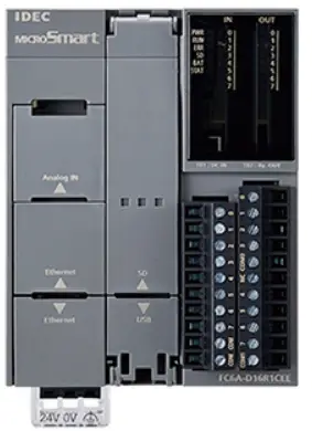
Parts Description

- Module label Indicates the module Type No. and specifications.
- LED Indicator Turns on when power is supplied to the analog I/O module./ For PID modules ony, turns on in conjuction with the status.
- Terminal No. Indicates terminal numbers.
- Cable Terminal These terminals connect output devices, input devices or power.
- Expansion Connector Connects to the CPU and other I/O modules.
Connecting Modules

- When connecting an input or output module, remove the expansion connector seal from the CPU module.
- Place the CPU module and Analog I/O module / PID module side by side. Put the expansion connectors together for easy alignment.
- correctly and the unlatch button in the down position, press the CPU module and Analog I/O module / PID module together until the latches click to attach the modules together firmly. If the unlatch button is in the up position, push down the button to engage the latches.
CAUTION
When an expansion module is not connected next, don’t peel off the protection sticker.
Mounting Modules
For details about mounting and removing modules, see the user’s manual. [Mounting on DIN Rail] Use a 35-mm-wide DIN Rail and BNL6 mounting clips to secure the modules.


Attach the module to the mounting plate using M4 tapping screws, as shown below, or make 5 to 6mm mounting holes and secure the module using M4 pan head screws. Always give sufficient consideration to operability, ease-of maintenance, and environmental resistance when deciding on the mounting position.

FC6A-J2C1, FC6A-J2C4, FC6A-J4A1, FC6A-J4A4, FC6A-J8A1, FC6A-J8A4, FC6A-J4CN1, FC6A-J4CN4, FC6A-J8CU1, FC6A-J8CU4, FC6A-K4A1, FC6A-K4A4, FC6A-L03CN1, FC6A-L03CN4, FC6A-L06A1, FC6A-L06A4, FC6A-K2A1, FC6A-K2A4, FC6A-J4CH1Y, FC6A-J4CH4YFC6A-F2M1, FC6A-F2M4, FC6A-F2MR1, FC6A-F2MR4
CAUTION
For UL/cUL, Horizontal mounting only.
Dimensions

Wiring


OUT 0 shows an example of connecting a relay output. OUT 1 shows an example of connecting non-contact voltage/current outputs. There is no PID module available with both outputs.Wiring for 2-wire analog out sensor

CAUTION
- Use a Class 2 or SELV power supply source when power supply voltage less than 30V DC is required to power the terminal.
- Use copper conductor only.
- Do not use analog output current from the FC6A-L03CN1 / 4 in a Surrounding Air Temperature 65°C. See the user’s manual for details.
Applicable Cable / Recommended Ferrule /Recommended Screwdriver / Tightening Torque
The recommended ferrule is made by Phoenix Contact or Weidmüller. To crimp the ferrules shown below, use a special crimping tool. (CRIMPFOX6 (1212034) or PZ 6 Rote L (1444050000)) To the terminal block, use the recommended screwdriver made by Phoenix Contact or Weidmüller and tighten terminal screws tightening torque. F6A-J4A1, F6A-J4A4, FC6A-J4CH1Y, FC6A-J4CH4Y, FC6A-J4CN1, FC6A-J4CN4, FC6A-J8A1, FC6A-J8A4, FC6A-J8CU1, FC6A-J8CU4, FC6A-L06A1, FC6A-L06A4, FC6A-F2M1, FC6A-F2M4, FC6A-F2MR1, FC6A-F2MR4 :

Precaution for Disposal
Dispose of the FC6A Series MICROSmart as an industrial waste. MicroSmart User’s manual can be downloaded from http://www.idec.com/FC6Amanuals
Documents / Resources
 |
EUIDEC B-1845 Micro Smart Plus CPU Module 24V DC Transistor Sink [pdf] Instructions B-1845, Micro Smart Plus CPU Module 24V DC Transistor Sink |


