![]()
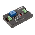
DC 12V Programmable
Time Delay Relay Module
SKU: U6030

This programmable multifunction time delay relay module is designed for different kinds of control systems. It has 18 preset modes, users can program one of the mode and its parameters to fit for their applications. The four keys are used for programming the relay module, the four segment LED display are used for displaying the mode and timing information.
SPECS
| Working voltage | DC 12V |
| Static current | 5.5mA |
| Temperature limitation | -30 -70 degrees (-20-60 degree recommended) |
| Load capacity | DC 30V or AC 250V / DC 28V or AC 125V |
| Load current | 10A |
| Max. frequency | ≤5KHz |
| Overall dimension | 66*40*20mm |
| Mounting hole pitch | 59*33mm |
WIRING & PART INSTRUCTION

- 4 blue LED indicators of 4 parameters
- DC power supply –
- DC power supply +
- Power LED
- 4 press buttons
- 4 digit display
- Neutral wires(N) of AC power or DC power supply –
- FireWire(L) of AC power or DC power supply +
• Terminal Blocks Explanation
| Input | DC+ | DC 12V power supply + |
| DC- | DC 12V power supply – | |
| CH1 | 3-30V high level voltage | |
| Output | NO | Normally open, disconnected when the timer off, short circuited |
| COM | Common interface | |
| NC | Normally closed, short circuited with COM when the timer off, |
• Press Buttons Explanation
In Working Mode Default mode when powered on | |
| SET | Short press to enter power saving mode, turn off the display, operate normally; Long press to enter setting mode, the timer will stop operating and enter the initial status. |
| SWI | Long press to enter view mode. |
| NUM+ | Long press to set/cancel the function of entering power saving mode automatically if there is no any operation for 10s, the display will flash twice if setting finished. Short Press SET to recover display briefly. |
| NUM- | Long press to reset/recover the current mode and stop operating |
In View Mode | |
| SET | Short press to switch the parameters |
| SWI | Long press to exit the view mode and enter the working mode |
In Setting Mode | |
| SET | Short press to switch the setting parameter, the corresponding LED will light; Long press to save the parameters and enter the working mode. |
| SWI | Short press to switch the digits, the selected digit will flash. Long press to set/cancel the decimal digits when setting T1 or T2. |
| NUM+ | Short press to increase the digit value. |
| NUM- | Short press to decrease the digit value. |
• 4 Blue LED Indicators Explanation
MO – the MODE OF THE TIMER. Set to between 1 and 18 based on how you want the timer to work. Mode 1-8 are self-starting upon power-on, while mode 9-18 require a high level pulse signal to trigger start-up and the high level need to be longer than 20ms.
T1 – FIRST TIME PERIOD DELAY. Based on the mode selected, this is the delay from first receiving the input trigger pulse until the second action happens. Look at the graphs in the next chapter for further explanations.
T2 – SECOND TIME PERIOD DELAY. Based on the mode selected, this is triggered by the completion of the T1 delay. T2 determines the delay until the next action happens.
NX – NUMBER MULTIPLIER & DELAY CYCLE INDEX. In the modes of 1 to 6 and 11 to 16, it’s used to set the values of T1 and/or T2 to greater than 9999 seconds. The default value of NX is 0101. To determine the actual time delay, T1 is multiplied by the first two digits of NX. The resulting value is the delay in seconds used by the timer. Similarly, the last two digits of NX are the multiplier for T2. In the modes of finite loops (mode 7/8/17/18), NX is also the cycle index.
TIMING CHART of MODES
| MODE 1 On Delay |  |
| MODE 2 Off Delay |  |
| MODE 3 On Delay & Off Delay |  |
| MODE 4 Off Delay & On delay |  |
| MODE 5 Infinite Loop of On Delay |  |
| MODE 6 Infinite Loop of Off Delay |  |
| MODE 7 Finite Loop of On Delay |  |
| MODE 8 Finite Loop of Off Delay |  |
| MODE 9 Self-locking Relay |  |
| MODE 10 Triggered On, and Off Delay after the CH1 signal disappearing |  |
| MODE 11 Triggered On Delay |  |
| MODE 12 Triggered Off Delay |  |
| MODE 13 Triggered On delay & Off delay |  |
| MODE 14 Triggered Off Delay & On Delay |  |
| MODE 15 Triggered Infinite Loop of On Delay and Off Delay |  |
| MODE 16 Triggered Infinite Loop of Off Delay and On Delay |  |
| MODE 17 Triggered finite Loop of On Delay and Off Delay |  |
| MODE 18 Triggered finite Loop of Off Delay and On Delay |  |
QUICK START GUIDE
Setting example: Delay on a light after 5s.
Step 1. Select the right working mode: Mode 1
Step 2. Long press SET to enter Setting mode; (at this moment the segment LED display starts to flash at the far right)
Step 3. Short press SET to select parameters of MD; (at this moment the LED near MD turn on constantly)
Step 4. Short press NUM+/NUM-, enter 0005, the value of segment LED display, that means 5s. Short press SWI to move cursor among 4 segment LED displays;
Step 5. Long press SET to exit the Setting mode and enter working mode.
CONTACT US
If any problem, please feel free to contact us.
Website: www.uctronics.com
Email: support@uctronics.com
Documents / Resources
 | UCTRONICS U6030 DC 12V Programmable Time Delay Relay Module [pdf] User Guide U6030 DC 12V Programmable Time Delay Relay Module, U6030, DC 12V Programmable Time Delay Relay Module |