Enlighted SU-6E-2W Micro Sensor Installation Guide

Shipped Components
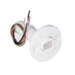
- Enlighted Micro Sensor, (SU-6E-2W)
Supplemental Components
- Tile Mount Carrier (TMC-SU-5E)*
- Hard Ceiling Mount Carrier (HCMC-SU-5E)*
- 18 AWG (0.75 mm2) solid copper wire
Tools you may Need
- 7/8” or 23 mm Drill bit (1/2” or 13 mm knock out trade size)
- Hand drill
- Wire stripper
* Sold separately. Contact Enlighted Customer Support.
Caution
A qualified electrician must perform installation and maintenance under local, state, and national electrical codes (NEC) and requirements. For installations outside of North America, qualified personnel must conform to appropriate standards when installing and maintaining products powered by FELV circuits, such as some DALI installations.
Warning
![]() FELV circuits are not safe to touch.
FELV circuits are not safe to touch.
 Isolate the circuits connected to any FELV source from the AC mains supply of the control gear.
 Ensure to protect the FELV circuit from any accidental contact.
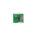
- When installing the Radio Module, de-energize the FELV source and any AC main sources near the FELV.
- Place the Radio Module in a luminaire or other suitable enclosure only (when powered by FELV).
- Circuits connected to any FELV control terminal must be insulated for the LV supply voltage of the control gear, and all terminals connected to the FELV circuit must be protected from accidental contact.
- To avoid the possibility of exceeding the FCC and ISED radio frequency exposure limits, human proximity to the radiator shall not be less than 20cm during normal operation.
Fixture Mount Sensor Installation
Step 1: De-energize the luminaire.
Note: For fixture mounting, use the fixture carrier and nut that is shipped with the sensor. The fixture mount can accommodate up to 0.25” (6.35 mm) thickness materials.

Step 2: Determine the location for the sensor in the fixture and drill a ½ inch (7/8” or 23 mm diameter) knockout in the fixture.

Step 3: Insert the fixture carrier through the hole in the fixture
Step 4: From behind the fixture, align the tabs of the nut with the keys on the fixture carrier

Step 5: Slide the tabs of the nut along the keys of the carrier to fasten the carrier.

Step 6: Cut two lengths of 18 AWG (0.75 mm2) solid wire of the required length. Strip insulation from each end of the two wires leaving 5/16 in (8 mm) of exposed wire.

Step 7: Insert one end of the pair of wires through the hole in the fixture and connect the wires to the sensor.
Step 8: Guiding the wire from above, push the sensor into the carrier until it securely clicks into the carrier.
Step 9: Leave four inches of slack cable in the sequence loop to avoid pinching of the cable and to bring the sensor down if it needs to be replaced.
Note: Do not pull the cable forcefully as this might damage the cable or connector.
Step 10: See section Connecting the Cable to the LED Driver.
Tile Mount Sensor Installation
Note: For tile mounting*, the tile carrier and nut must be ordered separately. The tile mount can accommodate up to 1.5” (38 mm) thick tiles.

Step 1: De-energize the luminaire.
Step 2: Make a 7/8“ or 23 mm diameter hole in the ceiling tile.
Step 3: Insert the tile carrier through the hole into the tile.

Step 4: Thread the plain end of the nut from behind the tile to secure the carrier.
If the tile is thicker than normal, flip the nut and thread the ribbed end of the nut to secure the carrier.

Step 5: Cut two lengths of 18 AWG (0.75 mm2) solid wire of the required length. Strip each end of the two wires leaving 5/16” (8 mm) of exposed wire.
Step 6: Insert one end of the wires through the hole in the tile and connect the wires to the sensor.

Step 7: Guiding the wire from above, push the sensor into the carrier until it securely clicks into the carrier.

Step 8: Leave four inches of slack cable in the sequence loop to avoid pinching of the cable and to bring the sensor down if it needs to be replaced.
Note: Do not pull the cable forcefully as this might damage the cable or connector.
Step 9: See section Connecting the Cable to the LED Driver.
Connecting the Cable to the LED Driver
Step 1: Connect the pair of wires to the LED Driver.

Step 2: Turn the power on by switching on the circuit breaker and wait for the green LED to appear.
LED Description
Note: The purpose of wiring test is to serve as a sanity check regarding connectivity to the sensor. However, the overall responsibility of the quality of the device must meet the QC criteria for the light fixture manufacturer.
| LED Status | Description/Solution |
| LED not on | The sensor is not powered on. Check power and wiring |
| Blinking Green | The commissioned sensor has powered up and has detected motion. If there is no motion in the sensor’s field of view, the blinking will stop. Wave your hands below the sensor to restart LED blinking. |
| Solid Green | The uncommissioned sensor has powered up successfully and completed the wiring test with no unexpected conditions – waiting for discovery. |
| Blinking Red | The uncommissioned sensor has powered up and completed the wiring test with one or more conditions unexpected of a typical LED fixture – waiting for discovery. |
| Solid Red | Faulty sensor – replace the sensor. |
| Solid Blue | Sensor received a request to identify itself. |
| Blinking Blue | The uncommissioned sensor powered up successfully, but the sensor is unable to detect an energy measurement device (CU or Driver), waiting for discovery. |
| Blinking Magenta | When the sensor is connected to a DALI emergency driver that is currently in the process of an emergency test or an emergency test pending. |
| Interrupted Green | Un-commissioned fixtureless sensors. |
Company Contact Information
Location: 3979 Freedom Circle, #210,
Santa Clara, CA 95054
Phone: +1.650.964.1094
Web: enlightedinc.com
DoCs: https://www.enlightedinc.com/eu-docs/
Support Portal: support.enlightedinc.com
Model No. SU-6E
Product Code: SU-6E-2W
Power: 180 mW
FCC ID: AQQ-SU6E
IC: 10138A-SU6E
HVIN: 01-03335-03

This device complies with Part 15 of the FCC Rules and Innovation, Science and Economic Development Canada’s license-exempt RSS standard(s). Operation is subject to the following two conditions:
- This device may not cause harmful interference, and
- This device must accept any interference received, including interference that may cause undesired operation of the device.
Changes or modifications not expressly approved by Enlighted could void the user’s authority to operate the equipment.
Copyright © Enlighted Inc. All rights reserved.
All other brand or product names are trademarks of their respective companies or organizations.

Documents / Resources
 |
Enlighted SU-6E-2W Micro Sensor [pdf] Installation Guide SU-6E-2W Micro Sensor, SU-6E-2W, Micro Sensor, Sensor |