Embedded Lab RXD-UR2EM-01 Multiple Connected Self Organizing Network Communication Modules
Product Information
Specifications
- Product Name: RXD-UR2EM-01
- Product Type: Wireless multi-connectivity self-organizing network photovoltaic motor communication module
- Communication Protocol: RS485, relay communication
- Power Supply: 5V
- Size: 60*130*30mm
- Antenna Interface: Built-in board PCB antenna
- Debugging Interface: 2.54mm 1x8P test point
- Communication Interface: HX20007-4AWB flat tape clip (2.00mm 1x4P)
Product introduction
Wireless multi-connectivity self-organizing network photovoltaic motor communication module is a wireless communication product dedicated to industrial site collection and industrial equipment control. It supports relay communication and RS485 bus.
The product uses the Ewei interconnection technology, combined with the interconnection base station, to support RS485 data collection and upload, wireless sending of device control information to designated devices and other functions.
It can be applied to sensor timing collection, PLC equipment control, and can achieve wireless control of multi-node devices in industrial sites based on sensor and control information. At the same time, it can realize relay transmission to expand communication coverage, save wiring construction costs, achieve wireless multi-point information collection and equipment control, which can help simplify industrial site wiring, reduce implementation difficulty, and save renovation costs.
Product features
- Product features: RS485 Communication
- Product function: support 5V power supply, RS485 interface
- Application scenario: wireless on-site communication without wiring
- Other features: support for relay communication
Main application scenarios
In conjunction with ZhiXinDa communication positioning base stations, it can achieve RS485 data collection and upload as well as wireless device control information transmission. Suitable for sensor timed collection and PLC equipment control, based on sensor and control information, it realizes wireless control of multi-node devices in industrial sites. This method can reduce cabling costs, simplify on-site wiring, reduce implementation difficulty, and save renovation costs.
Block diagram

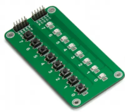
Size of product
Modulesize
60*130*30mm, line length 1200mm 
Product interface
Antenna interface
| Parameter item | define |
| Antenna interface | Built-in board PCB antenna |
Debugging interface
Internal debugging interface type: 2.54mm1x8P test point The internal debugging interface is defined as follows:
| order number | parameter | define |
| PIN 1 | REST | reset |
| PIN 2 | UART_TX | Debug serial port sending |
| PIN 3 | UART_RX | Debug serial port reception |
| PIN 4 | +3.3V | +3.3 V power supply |
| PIN 5 | GND | the earth |
| PIN 6 | SWDCLK | Debug interface-clock |
| PIN 7 | SWDIO | Debug interface-data |
| PIN 8 | BOOT | Start mode Settings |
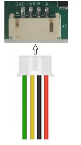
Communication interface
Interface model: HX20007-4AWB flat tape clip (2.00mm1x4P flat tape installation)
The communication interface is defined as follows:
| order number | parameter | define |
| PIN 9 | GND | source GND |
| PIN 10 | +5V | Power supply +5V |
| PIN 11 | 485B | Communication interface 485 B |
| PIN 12 | 485A | Communication interface 485 A |
Interface matching connector model selection: PH series with a spacing of 2.00mm1x4P

The connection diagram is as follows:
Basic characteristics
Basic RF characteristics
| Parameter item | define |
| service frequency | 2.4GHz ISM band |
| Wireless standards | 2.4G private protocol |
| rate of data signalling | 1Mbps |
| Antenna interface | Built-in onboard antenna |
Antenna performance
Antenna gain
| Test Item | Test Result | Unit | |
|
Antenna gain |
2402MHz | 5.324 | dBi |
| 2404MHz | 5.474 | dBi | |
| 2444MHz | 5.329 | dBi | |
| 2480MHz | 6.279 | dBi | |
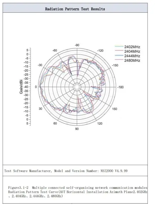
Antenna Radiation Pattern
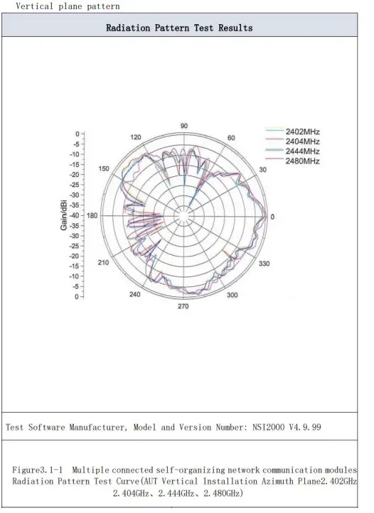
Horizontal plane pattern
RF output power
| Parameter item | least value | representative value | crest value | unit |
| RF average output power | – | 6 | 7 | dBm |
RF receiving sensitivity
| Parameter item | least value | representativ evalue | crest value | unit |
| RX sensitivity 1Mbps | – | -9 5 | – | dBm |
Communicating protocol
| Parameter item | content |
|
code |
8-bit binary |
|
start bit |
1 bit |
|
data bit |
8 bits |
|
parity check bit |
No parity check bits |
|
stop bit |
1 bit |
|
error check |
CRC (Redundant cyclic code) |
|
Baud rate |
9600、19200,38400,57600,115200 |
Principle lock diagram

Function declaration
Relay mode function
| Features | functional description |
| Relay forwarding | After the terminal is configured as a relay node, it should relay the communication information of the sub node according to the configuration information on the basis of retaining the original
communication capability |
| Data caching | Data caching is set up at the relay node to ensure that data can be transmitted in subsequent communications when a node is
temporarily disconnected. |
| Packet acknowledgment | Each relay node sends a confirmation signal after receiving the data packet to ensure that the source node knows that the data has been
successfully transmitted. |
| Automatic retransmission | In case of data packet transmission failure, automatic retransmission mechanism can be set to ensure that data can be effectively
transmitted |
| Signal strength
monitoring |
Nodes can regularly monitor the signal strength of surrounding nodes to dynamically adjust the selection of relay nodes and
optimize the communication link |
| Packet loss
handling |
Monitor and process packet loss and ensure data integrity through
retransmission or other mechanisms |
Terminal mode function
| Features | functional description |
| Control commands are
issued |
The control command can also be issued to the target node through multi-level jump, so as to ensure the reliable transmission
of the command |
| Data acquisition and
encapsulation |
Data is collected from sensors or devices and encapsulated into packets |
| Data segmentation
and assembly |
Divide the big data into small segments to facilitate transmission through multiple levels of links, and then reassemble them at the
target node |
| Data compression
and optimization |
In uplink communication, data can be compressed and optimized to reduce the load of data transmission |
| Packet
sequence number |
Assign a sequence number to each data packet to ensure the order and integrity of the data |
| Packet acknowledgment | After receiving the data packet, the target node sends a
confirmation signal to the source node to ensure the status of data transmission |
| Data caching and retransmission | In case of transmission failure, the relay node or the target node can buffer the data and perform automatic retransmission |
| Priority
management |
For different types of data, priority can be set to ensure that critical data is transmitted first |
Precautions to be Observed
The working environment of the product is-30℃ ~ 60℃, away from the fire source and strong electromagnetic interference source.
This device complies with part 15 of the FCC Rules. Operation is subject to the condition that this device does not cause harmful interference.
This device is verified to comply with part 15 of the FCC Rules for use with cable television service.
This device complies with part 15 of the FCC Rules. Operation is subject to the following two conditions:
- This device may not cause harmful interference, and
- This device must accept any interference received, including interference that may cause undesired operation.
Note: This equipment has been tested and found to comply with the limits for a Class B digital device, pursuant to part 15 of the FCC Rules. These limits are designed to provide reasonable protection against harmful interference in a residential installation. This equipment generates, uses and can radiate radio frequency energy and, if not installed and used in accordance with the instructions, may cause harmful interference to radio communications. However, there is no guarantee that interference will not occur in a particular installation. If this equipment does cause harmful interference to radio or television reception, which can be determined by turning the equipment off and on, the user is encouraged to try to correct the interference by one or more of the following measures:
- Reorient or relocate the receiving antenna.
- Increase the separation between the equipment and receiver.
- Connect the equipment into an outlet on a circuit different from that to which the receiver is connected.
- Consult the dealer or an experienced radio/TV technician for help.
This equipment complies with radio frequency exposure limits set forth by the FCC for an uncontrolled environment.
This equipment should be installed and operated with a minimum distance of 10 cm between the device and the user or bystanders.
This device must not be co-located or operating in conjunction with any other antenna or transmitter.
This radio transmitter (IC: XXXX–ZZZZZZ) has been approved by Industry Canada to operate with the antenna types listed below with the maximum permissible gain indicated. Antenna types not included in this list, having a gain greater than the maximum gain indicated for that type, are strictly prohibited for use with this device. (Antenna Type:2.4G built-in on-board antenna、Antenna Gain<6.5)
This device contains licence-exempt transmitter(s)/receiver(s) that comply with Innovation, Science and Economic Development Canada’s licence-exempt RSS(s). Operation is subject to the following two conditions:
- This device may not cause interference; and
- This device must accept any interference, including interference that may cause undesired operation of the device.
This equipment should be installed and operated with a minimum distance of 20 cm between the device and the user or bystanders.
This device must not be co-located or operating in conjunction with any other antenna or transmitter.
CAN ICES-3 (*)/NMB-3(*)
Signature page
| fiction | proofread | examine and verify | standardization | ||
| sign | |||||
| date | |||||
|
countersign |
|||||
| unit | |||||
| sign | |||||
| date | |||||
| unit | |||||
| sign | |||||
| date | |||||
| ratify | |||||
|
|
|||||
| orde r | edition | stage | Person making | Change the date | Status description/change number |
| 1 | 0.2 | S | Zheng Defu | 2024.6.25 | |
|
2 |
|
|
|
|
|
| 3 | |||||
| 4 | |||||
| 5 | |||||
| 6 | |||||
| 7 | |||||
| 8 | |||||
| 9 | |||||
| 10 | |||||
| 11 | |||||
| 12 | |||||
| 13 | |||||
| 14 | |||||
| 15 |
QA
The factory has passed the ISO9001 quality system certification. Each product has been tested strictly (transmitting power test, sensitivity test, power consumption test, stability test, aging test, etc.).
Frequently Asked Questions
- Q: What is the power supply requirement for the RXD-UR2EM-01?
A: The product supports a 5V power supply. - Q: What communication protocols does the RXD-UR2EM-01 support?
A: The product supports RS485 communication and relay communication. - Q: What are the main application scenarios for the RXD-UR2EM-01?
A: The main application scenarios include sensor timing collection, PLC equipment control, and wireless control of multi-node devices in industrial sites.
Documents / Resources
 |
Embedded Lab RXD-UR2EM-01 Multiple Connected Self Organizing Network Communication Modules [pdf] Owner's Manual RXDUR2EM01, 2BLNO-RXDUR2EM01, 2BLNORXDUR2EM01, RXD-UR2EM-01 Multiple Connected Self Organizing Network Communication Modules, RXD-UR2EM-01, Multiple Connected Self Organizing Network Communication Modules, Connected Self Organizing Network Communication Modules, Self Organizing Network Communication Modules, Network Communication Modules, Communication Modules, Modules |