![]() SlimLine Compact Eth
SlimLine Compact Eth
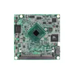
![]() CPU Module Hardware
CPU Module Hardware
Instruction Manual
IEC61131-3 SlimLine Compact Eth CPU Module
Connections
The SlimLine Compact Ethernet CPU module is provided of extractable TB to connect Power, I/Os and Field bus, IDC connector to connect the extension modules, RJ45 connectors for RS232 COM port and Ethertnet.
Power supply (Fig. 3)
The module can be powered with a DC source within the range 10-30Vdc. The power connection must be done according to the Fig. 2.
The power is signalized by the green LED “PWR”.
![]() WARNING! Values greater than the maximum allowed may damage the device seriously.
WARNING! Values greater than the maximum allowed may damage the device seriously.
Ground connection (Fig. 3)
The device must be connected directly to Ground using the terminal block on the power supply connector (Fig. 3).
The connection must be performed through a wire with section at least of 1.5mm², to a copper equipotential bar of adequate section.
To guarantee a good noise rejection, keep this connection as short as possible and take care to place it far away to the other cables.
Digital/Analog Inputs (Fig. 2)
The module is provided of 6 digital input and 2 analog input.
The digital input are galvanically insulated from the system and may be either PNP or NPN type as for your convenience.
The digital Input DI00 may be used as a counter input with Fmax=10KHz.
The analog Input are not insulated from the system and accept input voltages from 0 to 10Vdc.
![]() WARNING! To connect the analog input use EXCLUSIVELY shielded cables, taking care to avoid placements close to noise sources.
WARNING! To connect the analog input use EXCLUSIVELY shielded cables, taking care to avoid placements close to noise sources.
Digital Outputs (Fig. 7)
The module is provided of 4 Digital outputs Relay , static OptoMOS or SSR (according to the version), galvanically insulated from the system.
Static OptoMOS outputs may be either PNP or NPN type as for your convenience.
SSR outputs are provided of Zero-cross feature and can be used on AC load ONLY.
WARNING! Shorts on the outputs may damage permanently the device.
![]() For static OptoMOS versions it’s suitable to place an extra rapid fuse 1AFF in series of the output common (DOComx) (i.e. Ferraz J084004P).
For static OptoMOS versions it’s suitable to place an extra rapid fuse 1AFF in series of the output common (DOComx) (i.e. Ferraz J084004P).
For SSR versions it’s suitable to place an extrarapid fuse with I²T specification of 8A²s.
Extension bus (where provided) (Fig. 8)
The communication bus with the extension modules uses the I2C™ interface (Fast mode) and it’s available on the IDC10 connector (P7). The extension modules must be cascade connected through the special cables CBL074*000/CBL045**00 (to be ordered separately).
The Fig. 9 is an example of extension modules connection.
Up to 4 extension modules may be connected to the CPU (prior to check the maximum current needed).
![]() WARNING! Before to connect the extension modules to the system, be sure that it’s powered off. Missing this rule may produce failures in the modules.
WARNING! Before to connect the extension modules to the system, be sure that it’s powered off. Missing this rule may produce failures in the modules.
RS232 Serial port + USB (Fig. 7)
The device is provided of one serial port DTE (Data Terminal Equipment). The connection between DTEs, such as Personal Computers, Operator Terminals etc., must be done through a Nullmodem cable of maximum cable length of 15 mt, according to EIA specifications.
This port isn’t galvanically insulated from the system, it is recommended to verify, before to connect together different devices, the difference of potential on the ground.
![]() WARNING! An excess of difference of potential on ground loop may cause damages to the devices.
WARNING! An excess of difference of potential on ground loop may cause damages to the devices.
The USB port is available on Extended versions only, and meets 2,0 specifications.
USB connector is A Type (Host mode).
Ethernet port (Fig. 1)
The module is provided of an Ethernet 10/100-Base T(x) available on the RJ45 connector P2; the connection, shown in Fig. 1, are compatible with the standard Ethernet IEEE 802.3 100-Base T.
To connect the device in an Ethernet network must be used UTP Cat. 5 cables RJ45, connected to an HUB or a switch, while to made a point to point connection it’s enough to use an RJ45 patch cable without HUBs. The device is Auto-MDIX, so no cross cable is needed to connect it to a PC directly.
On P2 are available two LED for Ethernet status signaling: The green LED signals, when on, that the network is running at 100Mb/s speed.
The yellow LED signals the Ethernet link activity.
The module is supplied with DHCP enabled and, in case of lack of a DHCP server, the IP address can be assigned with the Toolly – Elsist.
![]() WARNING! The module is supplied with Admin user credentials: User “Admin” e password “Admin”. It is strongly recommended to change them before installation.
WARNING! The module is supplied with Admin user credentials: User “Admin” e password “Admin”. It is strongly recommended to change them before installation.
Status signaling (Fig. 5)
The device is provided of some LEDs to signal its status, particularly is signaled:
- PWR (Green LED)
Indicates that device is powered - RUN (Yellow LED)
Regularly blinking indicates that the system is running without errors, - RDY (Green LED)
When light indicates that the system is ready and it manages the I/O modules according to the user program.
When it’s off it resets the output status on extension modules eventually connected to the system. - DIxx (Red LED)
When light indicates activation of the corresponding DIxx. - DOxx (Red LED)
When light indicates activation of the corresponding DOxx.
I²C™ is a trade mark of NXP Semiconductors
Technical Specifications
| CPU Version | Relay | Static OptoMOS | SSR ZC | |
| Power Supply | 10-30Vdc 2W (1) | |||
| Power to Exp. bus | 5Vdc 1A max. | |||
| Processor | Cortex M7 300MHz, 2MB FlashEPROM, 384kB SRAM | |||
| Program memory | Base | 65 kB User program (2) (131kB Option) | ||
| Ext. | 131 kB User program (2) | |||
| Mass memory | 398 kB User data (2) on FlashEPROM 4 MB Min. 100.000 erasing/programming cicles/page |
|||
| Data backup memory | 6 kB User data (2) on FRAM 32 kB | |||
| Data memory | Base | 12 kB RAM User data (2) (20kB Option) | ||
| Ext. | 20 kB RAM User data (2) | |||
| File System | FAT32 modified | |||
| FTP Server | Yes | |||
| Real Time Clock (4) | Base | Yes, Backup time keeping optional (3) | ||
| Ext. | Yes, Battery backup time keeping (5 years min.) | |||
| USB I/F | Base | None | ||
| Ext. | USB 2.0, on USB A connector (host mode) | |||
| Digital Input | 6 Optoisolated PNP/NPN 5-30Vdc, 7mA@24V |
|||
| Counters | 1 connected to DI00 (FMax 10kHz) | |||
|
Analog Input |
2 * 0-10Vdc common mode (or 1 differential) Resolution: 12Bit | |||
| Conversion time: 1.1 mS (1 Ch) 2.2 mS (2 Ch) | ||||
| Digital Output | 4 Relay (5) 5A@250Vac/5A@30Vdc max. Mechanical life: Min. 2 x 10⁷ (at 180cpm) Electrical life: Min. 105 (2A 250Vac, 30Vdc, resistive load) Min. 5 x 10⁴ (2A 250Vac, 30Vdc, resistive load) (at 20cpm) |
4 OptoMOS (5) |
4 SSR Zero-Cross (5) 2Arms 20-240Vrms (-20 to 25°C), 1Arms (70°C) I2T for fusing: 8A2s Zero-Cross Turn-On Voltage: 20V min Latching Current: 100mA min |
|
| PWM | N/A | 2 connected on DO00/01 (FMax 1kHz) | N/A | |
| Ethernet I/F | RJ45 10/100base-T(x) Auto-MDIX | |||
| Expansion bus | I2C™ (Fast mode) | |||
| Nr. max. exp. modules | 4, (to be verified depending of type of module connected) | |||
| RS232 I/F | Ports | 1 * DTE on RJ45 connector | ||
| Baudrates | 300, 600, 1200, 2400, 4800, 9600, 19200, 38400, 57600, 115200 bps | |||
| Data bit | 7 or 8 | |||
| Stop bit | 1 or 2 | |||
| Parity | Even, Odd, None | |||
| Status indicators | Power, RUN, READY, I/O Status | |||
| Environment | Operating temperature: from -20 to +70°C | |||
| Storage temperature: from -40° to +80°C | ||||
| Relative Humidity: Max. 90% | ||||
| Dimensions and weight | Dimensions: 22.5 mm L x 101 mm W x 120 mm H | |||
| Weight: 150g | ||||
| Approvals | CE, RoHS | |||
| Notes | (1) Worst case (2) Firmware depending, Min. data retention 10years (3) Code PCK046*000/PCK052*000 (4) SNTP (Simple Network Time Protocol) supported (5) 1 common every 2Out (6) @10Vdc Rload=20Ohm |
|||
 http://www.elsist.it
Via G. Brodolini, 15 (Z.I.) 15033 CASALE M.TO (AL) ITALY
Phone +39-0142-451987 Fax +39-0142-451988
Internet: http://www.elsist.it
email: elsist@elsist.it
MNL197B100
Documents / Resources
 |
Elsist IEC61131-3 SlimLine Compact Eth CPU Module [pdf] Instruction Manual IEC61131-3 SlimLine Compact Eth CPU Module, IEC61131-3, SlimLine Compact Eth CPU Module, Compact Eth CPU Module, Eth CPU Module, CPU Module, Module |