![]() Elektor MultiCalculator Kit
Elektor MultiCalculator Kit
Construction and User Manual

20848 Multi Calculator Kit

Notice
This document is complementary to the information contained in the engineering background and discussions posted on the Elektor Labs website.
Web Links to these publications may be found in Section 10.
Disclaimer
The circuits described in the manual are for domestic and educational use only. All drawings, photographs, PCB layouts, and article texts are copyright Elektor International Media b.v. and may not be reproduced, transmitted, or stored in any form in whole or in part without the prior written consent from the Publisher. Patent protection may exist in respect or circuits and devices described here. The Publisher does not accept responsibility for failing to identify such patent(s) or other protection.
The Publisher also disclaims any responsibility for the safe and proper function of reader-assembled projects based upon or from schematics or information published in or in relation with this Manual.
Published by Elektor International Media b.v., PO Box 11, NL-6114-JG, Susteren, The Netherlands. www.elektor.com; www.elektormagazine.com.
Kit Contents
The kit contains the PCB and all parts stated in the Bill of Materials found in section 8.
The next photo shows the components in the kit except the enclosure.

 The following photos show the top and bottom side of the PCB in the kit.


Tools Needed
› Soldering equipment for through-hole components. Soldering iron with a relatively small tip.
› Cutting pliers
› Flat-jaw pliers
› Pozidriv or Phillips screwdriver (depends on the exact type of screws in the kit)
› Tool for hex screws (Allen wrench), HEX = 2 mm
› PC/laptop and color printer to print the 20 10 x 10 mm labels (TIFF file) for the switches.
› Scissors or sharp hobby knife to cut the labels to size
Assembling the PCB
Before soldering any components, first make three solder bridges as shown in the following photo.
 Now solder resistors R1…R14, D1 and D2.

Next, solder connector H1, capacitors C1, C2 and C3, the LED, and the LDR. Bend the lead of the LDR so it looks sideways. However, the body of the LDR should not be placed over the edge of the PCB. Then also solder Q1, Q2, IR receiver U2, and NTC R16.
 Now solder the 16-way socket for the LCD1 connector and the five pinheaders for the Pro Mini module U1. Two 12-way pinheaders are part of the Pro Mini package. In the package of the Pro Mini is also a right angle 6-way pinheader, but is not needed in the MultiCalculator. The other three pinheaders must be broken off (or cut) from the extra 12 way pinheader in the kit: 2-way, 3-way and 6-way, leaving one pin of it unused. Place the module on top of the 5 pinheaders when soldering them to the PCB or the module might not fit (due to tolerances). When all pins are soldered to the bottom side of the PCB, all pins can be soldered on the top side of the module.

After soldering the Pro Mini module, 3.5 mm jack J2 can be soldered as well.
 The switches can be inserted and soldered. First, solder the switch itself only and don’t fit the keytop and transparent cap on it for now.

Labels
The labels needed for the switches can be downloaded from the Project Elements. It’s up to you if you want to use standard or glossy paper. In case of the latter, print on standard paper first to get the size of the labels correct. The dimensions for the labels inside the transparent cap is 10 x 10 mm. A good start is printing the tiff file at 44 %.

Use scissors or a sharp hobby knife and a ruler to separate the 20 labelsFirst, place the keytops and then press the transparent caps with the labels inside onto the keytops. Of course, pressing the caps with the labels on the keytops first and then the entirety onto the switch is also possible, whichever you prefer.


Fitting the Display
Finally, the LCD can be mounted. First, push the 16-way 18.54 mm heigh male pinheader into the 16-way socket of LCD1. Place the display on the pinheader and press it gently down without bending or forcing anything, then solder the 16 pads on the top of the display. Use one of the 5 mm thick display support panels to check if the angle is correct, place it next to it. To power the MultiCalculator calculator, the wired USB-C connector must be soldered to the pads of J1 on the PCB. The wired USB-C connector can be soldered after the connector is pushed through the rear panel!

Programming the Module
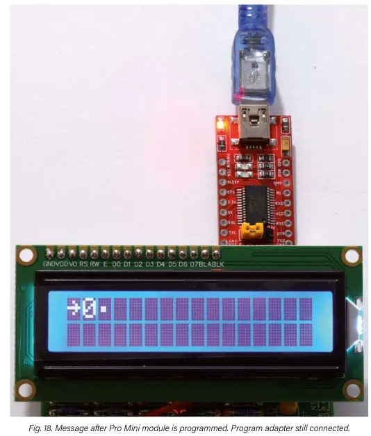
Module U1 requires programming using the Arduino IDE and some experience with that IDE, as well as programming modules and/or microcontrollers is assumed. Connect the programming adapter as pictured in Fig. 18. It will power the module U1 directly, meaning no extra supply has to be connected to the MultiCalculator. Download the Arduino sketch RM_MultiCalculator_Elektor_v1.1.ino from the Project Elements and place it in a directory called: RM_MultiCalculator_Elektor_v1.1. Open the sketch. The Arduino AVR Board “Arduino Pro or Pro Mini” has to be selected. For the processor, select “ATmega328P (5V, 16 MHz)”. See the screendump in Figure 17.
 Two extra libraries must be added to your own program directory:
Keypad-master and IR Read Only Remote-master. They are also located under Project Elements. After unzipping, copy the two directories to C:\
Users\your-user-name\Documents\Arduino\libraries or whatever location your installation is set up for.
After successfully programming the Pro Mini module a message should be displayed similar to this:
Sketch uses 21816 bytes (71%) of program storage space. Maximum is 30720 bytes.
Global variables use 1419 bytes (69%) of dynamic memory, leaving 629 bytes for local variables. Maximum is 2048 bytes.
Note: the message can be slightly different after a software update.
Assembling the Enclosure
The two sides of the hole for the wired USB-C socket in the back panel require a little filing out so the mounting springs of the socket will fit properly and secure the connector, preventing it from sliding out when a
USB connector is unplugged. The hole must not be widened! Instead two slots with a width of 3 mm and the correct angle must be made for the springs of the USB-C socket to expand in (see Figure 19) after pressing the connector through the hole, which takes some force. If the USB-C socket is pulled out of the hole when unplugging a connector consider gluing the socket to the panel.

Remove all the protective foils covering the panels on both sides. One foil may be colored while the other isn’t, and it might look there isn’t a foil at all. Look closely! Removing the foils can be done with a sharp hobby knife by carefully peeling off starting at one of the corners. Be careful not to scratch the panels.
Push the USB socket through the back panel. Then place the 2 mm screws with a small plastic washer in the bottom panel and mount the small 3 mm high standoffs over the 2 mm screws.

Solder the USB socket wires to the PCB (J1). Now fit the back panel over the 3.5 mm jack (J2) and 6-way SIL socket (H1). Also place the small display supports and place a nut and screw in each of the designated openings and holes in the back panel. Don’t tighten the screws yet. Hold the PCB with the two display supports and back panel and slide the PCB mounting holes over the M2 screws and the display supports and back panel in the slots in the bottom panel. Place a small plastic washer on each M2 screw, then fasten the PCB to the bottom panel with the 4 M2 nuts.

Place two M3x12 countersunk screws in the back panel and a 3 mm nut in each display support panel. Tighten the screws in the back panel, then fasten the M2 screws of the PCB (Fig. 22).
 Place the plastic 8 mm M3 standoffs on the bottom panel — two on each side of the PCB. Use the 4 6 mm M3 screws and the larger plastic washer (these go under the head of the screw). Mount the small front panel and the two side panels. Next, the U-shaped panel can be placed, which will support the top panel of the pushbuttons.

Now the dark acrylic panel for the pushbuttons can be placed and secured with 4 black countersunk M3x10 screws. If a hole next to the display is a little out of place, simply flip the U-shaped panel.

Place the small dark support for the display bezel on top of key panel. Put an M3 nut in each side next to the display. Place the display bezel over the metal frame of the display and into the two supports at each side of the display. Install two black M3x12 countersunk screws and tighten them.

Important:
If any of the pushbuttons fails to return after pressing, remove the keytops and rotate them to see if that helps. This may also apply to the transparent caps. Sadly, especially the keytops have just enough tolerance to make a few stick. Making all the holes in de dark top panel larger would be a simple solution to compensate for these tolerances but prevents the pushbuttons from aligning accurately. A keytop placed on a switch can rotate a little. Only consider filing one hole side as a last resort.


All that remains now is sticking the self-adhesive rubber feet to the bottom.
Bill of Materials
Resistors
R1,R2,R3,R4,R5,R7,R9,R10,R11,R14 = 10 kΩ, 167 mW, 1 %., body 1.9 x 3.4 mm
R6,R12 = 100 Ω, 250 mW, 1%, body 2 x 3.5 mm
R8,R13 = 1 kΩ, 167 mW, 1 %, body 1.9 x 3.4 mm
R15 = LDR GL5516, 5.4 x 4.4 mm, lead spacing 3.4 mm
R16 = NTC 10 kΩ, type 3950, 5% 10 kΩ
R17 = not needed
Capacitors
C1 = 100 nF, 50 V, 10 %, X7R, lead spacing 2.5 mm
C2,C3 = 10 µF, 25 V, 10 %, tantalum, lead spacing 2.5 mm
Semiconductors
D1,D2 = 1N4148, DO-35
LED = 3 mm (T1) LED, red
Q1 = KSA708YBU, TO-92
Q2 = 2N3904, TO-92
U1 = Mini Pro
U2 = TSOP14438
LCD1 = LCD module 16 x 2, Alphanumeric, 36 x 80 mm
Miscellaneous
J1 = USB-C socket, chassis mounted, wired, 9 x 16 mm
J2 = 3.5 mm headphone jack, PCB mount PJ-325
H1 = 6-way female header, right angle, pitch 2.54 mm
H2 = not needed
P1 = not needed
SW1-SW20 = 12x12x7.3mm Tactile Switches
SW1-SW20 = Keytop + clear cap for switches (cap is 11.8 mm square)
LCD1 = 16-way male pinheader, height 18.54 mm, pitch 2.54 mm, vertical
LCD1 = 16-way socket, pitch 2.54 mm, vertical
FT232 Pro Mini USB-C TTL Adaptor (with 3-pin 3.3V/5V selection)
U1 = 12-way pinheader, vertical, pitch 2.54 mm (for Pro Mini)
2 x NTC 10 kΩ, Waterproof Temperature Sensor 3950 10K, 1 m cable 3.5 mm plug
USB-A to USB-C cable, 1 m
PCB, Elektor no. 220684-1 v1.0
Enclosure
4 x screw, M2, 12 mm, steel
4 x spacer sleeve, cylindrical, L: 3mm, Øout: 5mm, polyamide
4 x nut, M2, steel
8 x washer, M2, D=5mm, H=0.3mm, polyamide
4 x screw, M3, 6 mm, steel
4 x washer, M3, D=7mm, H=0.5mm, polyamide
4 x standoff, M3, Female-Female, Øout: 6mm L:8 mm, polyamide
4 x screw, M3, 10 mm, Head: countersunk, hex (Allen) key, HEX 2mm, steel
4 x screw, M3, 12 mm, Head: countersunk, hex (Allen) key, HEX 2mm, steel
4 x nut, M3, Plating: black finish, H: 2.4mm, steel
4 x self-adhesive case foot; H: 3.8mm, transparent, polyurethane
6 panels made of 3 mm extruded acrylic transparent/clear sheet:
back panel, front panel, bottom panel, 2 side panels, U-shaped keyboard support panel 2 display support panels made of 5 mm extruded acrylic transparent/clear sheet 3 panels made of 3 mm cast acrylic umbra transparent sheet (dark brown): display bezel, small support for display bezel, keyboard panel
Specifications
Supply voltage: 5 V (USB-C)
Supply current: ≈ 28…32 mA
Pro Mini microcontroller module (ATmega328/5V/16MHz)
Arduino IDE programmable
2×16 Alpha-Numerical LCD (LCD 1602, display color blue, white text) 20 labeled pushbuttons 3.5 mm jack to connect external sensors
Operating temperature of waterproof sensors -40 to +85 °C 22 menus (software version 1.1)
Functions:
- Decimal floating-point calculation.
- Binary, hexadecimal, decimal calculation, ASCII character viewer.
- Temperature and delta-T measurement.
- Stopwatch with lap time.
- Resistor value decoder.
- Capacitive reactance (X c ) and inductive reactance (X ) calculation.
- Equivalent resistance calculation: parallel, series and supplemental.
- Light measurement in mV and Lux.
- Item counter.
- IR decoder for NEC codes.
- AWG calculation with maximum current calculation.
- Dice with roll simulation.
- Calculator customizing.
- Calibration of the temperature measurement (zero point correction).
- Large 1602 LCD, blue display color with white text.
Dimensions: 92 x 138 x 40 mm (including self-adhesive feet)
Web Links
MultiCalculator kit: https://www.elektor.com/20848
MultiCalculator project on Elektor Labs website: https://www.elektormagazine.com/labs/elektor-multicalculator-kit-220684
Schematic and PCB Layout


User Manual
Applies to: Firmware v1.1
General:
To switch on, keep the ON/AC button pressed for a few seconds until text appears on the display. By pressing “mode”, the mode of operation can be chosen. In this version, 22 modes of operation are available. By pressing the mode button longer, the mode function counts back. Switch off by pressing the ON button for more than 4 seconds. When the key is released, the MultiCalculator is turned off.

Floating point calculator — enter the first number with or without a comma, then the operation (divide (÷), multiply (x), subtract (–), add (+) ) and close off with = .
Now the result will be displayed. When another operation is immediately entered, the first number is used again. After the = comes the new result. The Root (SQR) key shows the square root (√) of the result.
The calculation range is 7 digits before the comma and 3 digits after the comma, i.e., equal to the maximum computing capacities of the Arduino floating-point calculation.

Resistors with four color bands can be “decoded” here.
Enter the colors (numbers), for example: yellow (4) purple (7) orange (3 zeros) gold (÷).
Immediately after entering the last color band, the value is displayed in Ω or kΩ. (47 kΩ, 5%).

Resistors with five color bands can be decoded here.
Enter the colors (numbers), for example: yellow (4) purple (7) green (5) red (2 zeros) brown (1).
Immediately after entering the last color band, the value is displayed in Ω or kΩ. (47.5 kΩ, 1 %).

Enter a decimal value. (max 7 digits). The Hexadecimal value is now displayed directly after the =. If the value is within the ASCII range (32-255), the ASCII character of the LCD character font is displayed as the last character of the first line. Above 127 the character is different from the standard ASCII table. With the + and – keys the value can be increased or reduced by 1 at a time.

Mode 5 – Hexadecimal to Decimal and Character (ASCII) conversion.

Enter a hexadecimal value (max 7 numbers / letters A-F).
A through F can be entered with these keys: A(.), B(=), C(+), D(-), E(x), F(÷).
The decimal value is now displayed directly after the =.
If the value is within the ASCII range (32-255), the ASCII character of the LCD character font is displayed as the last character of the first line. Above 127 the character is different from the standard ASCII table.

Enter a decimal value (max 3 digits). The binary value is now displayed immediately after the =.
If the value is within the ASCII range (32-255), the ASCII character is displayed as the last character of the first line. Above 127 the character is different from the standard ASCII table.

Enter a binary value (max 8 digits) (0 and 1 only). The Decimal and Hexadecimal values are now displayed directly after the =. If the value is within the ASCII range (32-255), the ASCII character is displayed as the last character of the first line. Above 127 the character is different from the standard ASCII table.

Mode 8 – Hz, nF, reactance X c calculation

X c = the reactance value (apparent resistance) of a capacitor.
Enter a frequency, e.g. 50 Hz (hertz) and enter = . Next, enter the value of the capacitor in nF (nano-Farad) e.g. 4700 nF (= 4.7 μF) and enter =. The apparent resistance (or reactance) is now shown in ohms (X c = 677.6 Ω).

X l = reactance value (apparent resistance) of an inductor. Enter a value of the frequency, e.g. 50 Hz (hertz) and enter =. Next, enter the value of the inductor, in μH (microhenry), e.g. 4700 µH (= 4.7 mH). The apparent resistance (reactance) is now shown in ohms. (X l = 1.5 Ω)

Mode 11 – Resistance calculation of two resistors connected in series

In this calculation, you can determine resistor R2 connected in parallel to a known resistor R1 by entering the desired parallel resistance Rv first, followed by the value of the known resistor R1. The resistance of R2 is calculated. Enter the value of Rv (max. 6 digits) followed by =. Enter R1 followed by a =. The value for R2 is displayed. Example: you want a resistance (Rv) of 50 Ω and you have a resistance (R1) of 60 Ω, then should connect a resistance of 300 Ω in parallel with R1 to get the desired resistance of 50 Ω.

This is a temperature measurement via the internal (or external) temperature sensor (NTC R16).
The NTC is a 10 kΩ type 3950. It can be placed on the front, between the keys or on the right side of the MultiCalculator (R17). Use R16 or R17 but not both as it would connect them in parallel. An external sensor can be connected to the yellow 3.5 mm plug. The sensor can be calibrated (in zero point), see function 22. A measurement is performed every second.
The last character in the first line alternates between ← and →.
Mode 14 – Differential temperature measurement T1&T2 and Delta (δ)

This is a dual temperature measurement using two external temperature sensors.
The NTCs for this are two wired, 10 kΩ, 3950 types. A 3.5-mm plug connected to two external sensors can be connected to 3.5 mm jack J2.
See mode 22 for zero point calibration.
T1, T2 and the temperature difference are displayed. A measurement is performed every second. The last character in the second line alternates between ← and →.
Mode 15 – Light measurement

Light measurement using an LDR. The LDR is a type 5516 with a 10 kΩ series resistance. The number of millivolts converted to LUX , is displayed.
This is a calculated value with limited accuracy. The LUX value has a substantial range, for example:
Sunlight = 100,000 LUX
Day light = 10,000 LUX
Cloudy day = 1,000 LUX
Dark day = 100 LUX
In-house darkness = 10 LUX
A measurement is performed every second. The last character in the first line alternates between ← and →.
Mode 16 – Stopwatch with lap time function

Start (Run) with (+) , pause (Pauz) again with (+), with = the Lap time is displayed. Pressing 0 resets the time to 00:00:00.0. The stopwatch keeps working even after selecting other modes.

Using the number input, a basic number can be entered e.g. 50.
Now the number can be increased or decreased with + or –.
The maximum is 9999999.
Mode 18 – Display IR NEC code from a remote control

IR receiver U2 (TSOP14438) is located on the left side. The decoding of NEC codes is handled by the software (no other code sets due to size of program). NEC codes are widely used. The LED next to the IR receiver is connected to its output and flashes when receiving a remote control signal. The display shows:
L: code read from the least significant bit
M: code read from the most significant bit
A: address
C: full code

This function covers conversion of AWG number (often mentioned on cables and wire) to mm diameter and mm surface area. The maximum current through the wire displayed based on 5A/mm 2 2 .
Note: the larger the AWG value, the thinner the wire. For example, AWG 22 is a wire with a diameter of 0.64 mm, a surface area of 0.33 mm and can carry 1.6 A max. The AWG system ranges from 1 to 40. The AWG number can be changed by pressing the + and – keys.

Rolling a dice can be done with +, now a rolling function is displayed. 5 values appear, the next value is always different. The last value is the one used. This is done 2 times and the total value (sum) is displayed as ∑.
Entering = omits the animation and immediately displays the results.

At startup, the “–RM- MultiCalc” is displayed.
On the second line, a greeting can be placed, which is stored in fixed memory.
With 8 (↑) and 2(↓) the desired character can be chosen.
With 4 (←) and 6 (→), the character in the row can be chosen.
Each entry is automatically saved after each change.
 This mode corrects the temperature measurements in modes 13 and 14.
C = 0 yields no correction. The correction value is in tenths of a degree, e.g.; 5 means 0.5 degree higher. By default, this should be set to 0 to give the uncorrected temperature measurement. The value for the correction can be changed by pressing + or –. The correction can be set to ZERO by keeping the MODE key pressed during power-up.

V1.2 – date 1-5-2024
© Elektor International Media b.v.
This manual is available as a downloadable PDF.
You can find this essential document at the following address: www.elektor.com/20848
Documents / Resources
 |
elektor 20848 Multi Calculator Kit [pdf] User Manual 20848, 20848 Multi Calculator Kit, Multi Calculator Kit, Calculator Kit, Kit |