Edge core AIS800-64O Data Center Ethernet Switch User Guide

Package Contents

- 64-Port 800 Gigabit AI & Data Center Ethernet Switch AIS800- 64O
- Slide-rail mounting kit—2 rack slide-rails and install guide
- AC power cord, type IEC C19/C20 (included with AC PSUs only)
- DC power cord (included with DC PSUs only)
- Documentation—Quick Start Guide (this document) and Safety and Regulatory Information
Overview

- 64 x 800G OSFP800 ports
- Management Ports: 1 x 1000BASE-T RJ-45, 2 x 25G SFP28, RJ-45 console, USB
- Timing Ports: 1PPS, 10 MHz, TOD
- System LEDs
- 2 x grounding screws
- 2 x AC or DC PSUs
- 4 x fan trays
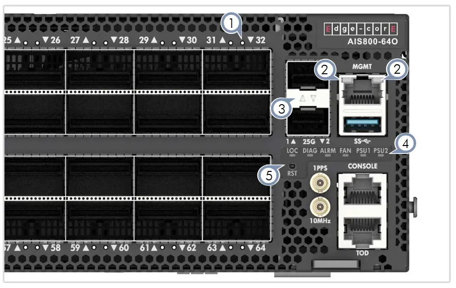
- OSFP800 LEDs: Purple (800G), Blue (400G), Cyan (200G), Green (100G), Red (50G)
- RJ-45 MGMT LEDs: Left: Green (link/act), Right: Green (speed)
- SFP28 LEDs: Green (link/activity)
- System LEDs:
LOC: Flashing Green (switch locator)
DIAG: Green (OK), Red (fault)
ALRM: Red (fault)
FAN: Green (OK), Red (fault)
PSU1/PSU2: Green (OK), Red (fault) - RST: Reset button
FRU Replacement

PSU Replacement
- Remove the power cord.
- Press the release latch and remove the PSU.
- Install replacement PSU with matching airflow direction.

Fan Tray Replacement
- Pull the handle release latch.
- Remove the fan tray from the chassis.
- Install a replacement fan with matching airflow direction.
![]() Caution: During switch operation, fan replacement should be completed within two minutes to prevent the switch shutting down due to its built-in over-temperature protection.
Caution: During switch operation, fan replacement should be completed within two minutes to prevent the switch shutting down due to its built-in over-temperature protection.
Installation
![]() Warning: For a safe and reliable installation, use only the accessories and screws provided with the device. Use of other accessories and screws could result in damage to the unit. Any damages incurred by using unapproved accessories are not covered by the warranty.
Warning: For a safe and reliable installation, use only the accessories and screws provided with the device. Use of other accessories and screws could result in damage to the unit. Any damages incurred by using unapproved accessories are not covered by the warranty.
![]() Caution: The device must be installed in a restricted-access location.
Caution: The device must be installed in a restricted-access location.
![]() Note: The device has the Open Network Install Environment (ONIE) software installer preloaded, but no device software image.
Note: The device has the Open Network Install Environment (ONIE) software installer preloaded, but no device software image.
- Mount the Device
 Caution: This device must be installed in a telecommunications room or a server room where only qualified personnel have access.

Using the Slide-Rail Kit
Follow instructions in the install guide provided in the slide-rail kit to mount the device in a rack. Note: Stability hazard. The rack may tip over causing serious personal injury.
Before extending the rack to the installation position, read the installation instructions.
Do not put any load on the slide-rail mounted equipment in the installation position.
Do not leave the slide-rail mounted equipment in the installation position. - Ground the Device

Verify Rack Ground
Ensure the rack on which the device is to be mounted is properly grounded and in compliance with ETSI ETS 300 253. Verify that there is a good electrical connection to the grounding point on the rack (no paint or isolating surface treatment).Attach Grounding Wire
Attach a grounding wire to the grounding point on the device rear panel using two M6 screws and washers with a grounding lug (Panduit LCDXN2-14AF-E or equivalent, not included). The grounding lug should accommodate #2 AWG stranded copper wire (green with yellow stripe, not included). - Connect Power

Install one or two AC or DC PSUs and connect them to an AC or DC power source.
Note: When using only one AC PSU to power a fully loaded system, be sure to use a high-voltage source (200–240 VAC).
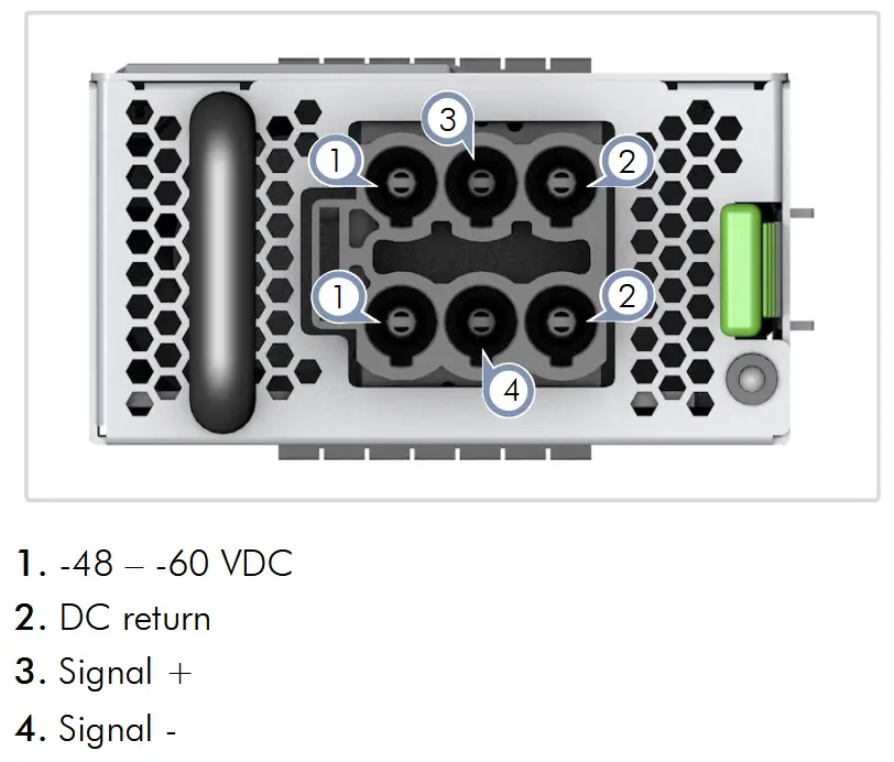
Caution: Use a UL/IEC/EN 60950-1 and/or 62368-1 certified power supply to connect to a DC converter.
Caution: All DC power connections should be performed by a qualified professional.
Note: Use #4 AWG / 21.2 mm 2 copper wire (for a -48 to -60 VDC PSU) to connect to a DC PSU. - Make Network Connections

800G OSFP800 Ports
Install transceivers and then connect fiber optic cabling to the transceiver ports.
Alternatively, connect DAC or AOC cables directly to the slots
- Connect Timing Ports

1PPS Port
Use a coax cable to connect the 1-pulse-per-second (1PPS) port to another synchronized device.
10 MHz Port
Use a coax cable to connect the 10 MHz port to another synchronized device.
TOD Port
Use a shielded cable to connect the Time-of-Day (TOD) RJ-45 port to other devices that use these synchronization signals. - Make Management Connections

25G SFP28 In-Band Management Ports
Install transceivers and then connect fiber optic cabling to the transceiver ports.10/100/1000M RJ-45 Out-of-Band Management Port
Connect Cat. 5e or better twisted-pair cable.RJ-45 Console Port
Use an RJ-45-to-DB-9 null-modem console cable (not included) to connect to a PC running terminal emulator software. Use a USB-to-male DB-9 adapter cable (not included) for connections to PCs that do not have a DB-9 serial port.Configure the serial connection: 115200 bps, 8 characters, no parity, one stop bit, 8 data bits, and no flow control.
Console cable pinouts and wiring:

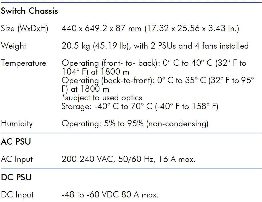
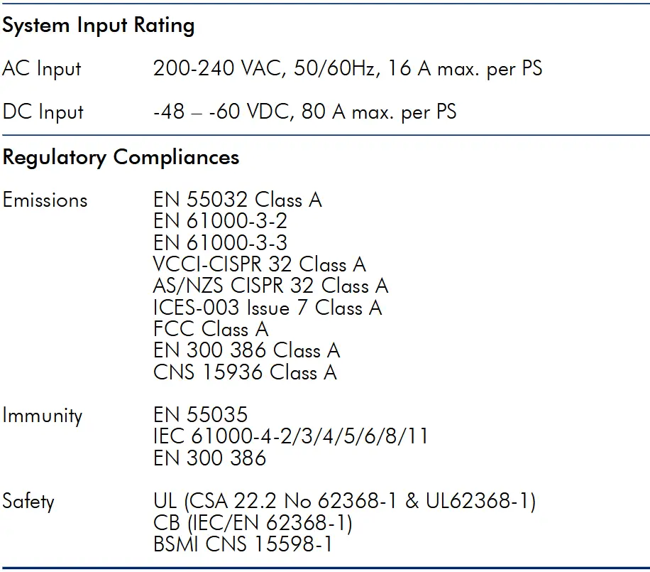
Hardware Specifications
Documents / Resources
 |
Edge core AIS800-64O Data Center Ethernet Switch [pdf] User Guide AIS800-64O, AIS800-64O Data Center Ethernet Switch, AIS800-64O, Data Center Ethernet Switch, Center Ethernet Switch, Ethernet Switch, Switch |