ECUMASTER USB to CAN Module User Manual
Device description
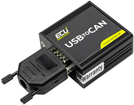
The USB to CAN interface is a tool used for communication and working with E cubmaster devices.
It allows you to connect and configure both main devices and accessories through the CAN protocol.
Main devices like the EMU PRO, PMU, and ADU are configured using dedicated software clients specifically designed for each device. Accessories (e.g., GPStoCAN, CAN Thermal Cameras) are set up using a Light Client, which provides a simpler interface. For detailed instructions on configuring each Ecumaster device, please refer to the corresponding manual.
Additionally, the USBtoCAN interface can be used as a CAN sniffer to monitor CAN messages, although this functionality is limited to the Light Client (https://www.ecumaster.com/files/ LightClient/LightClientManual.pdf).
![]() Note:
Note:
Ecumaster EMU Black and EMU Classic are not compatible with the USB to CAN interface.
These devices are configured directly via a USB cable instead.
The Ecumaster USB to CAN is equipped with a 120 Ohm terminator that can be used for CAN bus termination. If you are not using an external terminator, it is necessary to use the one provided by USB to CAN interface, otherwise the communication will not work. The USB to CAN terminator can be turned on or off using a switch on the casing.
The Ecumaster USBtoCAN indicates its current state using the three LEDs on its side. The table below shows all possible states and their corresponding LED colors:
| Color | Description |
| Green Continuous | Device turned on |
| Green Flashing | Device turned on and connected to PC |
| Green and Orange Flashing | Data transfer in progress |
| Orange Continuous | Device turned on, currently in bootloader |
| Orange Flashing | Device turned on, firmware update in progress |
| Red Continuous | Temporary CAN communication error |
| Red Flashing | Permanent CAN communication error |
Specification
| Dimensions | 54 x 55 x 24 mm |
| Weight | 80 g |
| CAN bus connector | DB9 |
| PC connector | USB type B |
| Status indicator | 3 LEDs |
| Temperature range | -40°C to +85°C |
| Operating supply voltage | 5 V from the USB connection |
All dimensions in mm

Pinout and Wiring
To connect the USB to CAN for communication, you only need to wire CAN high and CAN low.
- Solder the CAN low wire to pin 2 of the DB9 connector.
- Solder the CAN high wire to pin 7.
![]() Note:
Note:
The CAN interface is powered through the USB port and does not require an external power source. The +5V pin can be used to provide USB power for additional devices.

Example connection diagram:

![]() Attention:
Attention:
When powering other devices via USB to CAN, ensure proper grounding. A ground wire connection between the USB to CAN interface and other CAN devices can be dangerous!
Ground connections are only allowed if the devices have the same ground potential before connecting. To ensure safety, check for any potential difference by using a voltmeter to measure between the corresponding grounds.
Connecting to PC
To use Ecumaster USBtoCAN interface, user must be equipped in following items:
- USB A to USB B adapter to connect the interface to PC (Not included in the package)
- DB-9 Cable to connect interface to PMU
- Windows 10 should install Ecumaster USBtoCAN drivers automatically
- If using windows XP/7/8/8.1 – Ecumaster USBtoCAN interface drivers, available at: https:// ecumaster.com/products/usb-to-can/
To install drivers, run EUSBtoCAN_Driver_vX.X.exe and follow instructions.
Switching the USBtoCAN between Ecumaster devices
From software version:
- EMU PRO Client – 0 Alpha
- PMU Client – 0
- ADU Client – 4
- Light Client – 7
it is possible to switch easily between programmes without having to close one to open another.

When opening a program (e.g., PMU Client) while another program (e.g., Ecumaster Light Client) is already active, a prompt will automatically appear, asking whether the new program (PMU Client) should take control of the USBtoCAN adapter.

The program that was in use (Ecumaster Light Client) will then lose connection and become inactive.
When the program is called back to the foreground, a message will automatically appear indicating that the previously lost connection can be restored.
Document history
| Revision | Date | Changes |
| 1.0 | 2017.08.30 | Initial release |
| 2.0 | 2024.09.26 | Document layout changed to the Ecumaster standard formatAdditional details and images have been added for better clarity |
©Ecumaster | USER MANUAL | Published on: 26 September 2024 | Document version:
![]() www.ecumaster.com
www.ecumaster.com ![]() ecumaster_official
ecumaster_official ![]() ecumaster
ecumaster
Documents / Resources
 |
ECUMASTER USB to CAN Module [pdf] User Manual USB to CAN Module, Module |


