EBYTE ME31-AXAX4040 I/O Networking Module User Manual

All rights to internet and modify this manual belong to Chengdu Ebyte Electronic Technology Co.,Ltd.
Product Overview
Product introduction
ME31- AXAX4040 is equipped with 4-way A-type relay output and 4 -way dry contact input detection , supports Modbus TCP protocol or Modbus RTU protocol for acquisition control, and the device can also be used as a simple Modbus gateway (automatically convert non-local Modbus The command of the address is sent through the serial port/network port) of the network I/O networking module .

Features
- Support standard Mod b us RTU protocol and Mod b us TCP protocol ;
- Support various configuration software/PLC/touch screen;
- RS485 acquisition control I/O;
- R J45 acquisition and control I /O , support 4- way host access;
- 4- way switch input DI (dry node);
- 4-way switch output DO ( Form A relay);
- Switch output (DO) supports level mode, pulse mode , follow mode, reverse follow mode, trigger flip mode ;
- Support custom Modbus address setting;
- Support 8 common baud rate configurations;
- Support DHCP and static IP ;
- Support DNS function, domain name resolution;
- Support Modbus gateway function;
- Support input and output linkage;
Application Topology Diagram

Quick Start
[Note] This experiment needs to be carried out with the default factory parameters.Devices required
The following table lists the materials required for this test:

Device connection
RS485 connection

Note: When the 485 bus high-frequency signal is transmitted, the signal wavelength is shorter than the transmission line, and the signal will form a reflected wave at the end of the transmission line, which will interfere with the original signal. Therefore, it is necessary to add a terminal resistor at the end of the transmission line so that the signal does not reflect after reaching the end of the transmission line. The terminal resistance should be the same as the impedance of the communication cable, the typical value is 120 ohms. Its function is to match the bus impedance and improve the anti-interference and reliability of data communication.
DI digital input connection

Relay output connection

easy to use

Wiring: The computer is connected to the RS485 interface of ME31 – AXAX4040 through USB to RS485 , A is connected to A, and B is connected to B.
Networking: the network cable is inserted into the R J45 port and connected to the PC .
Power supply: use DC – 1 2V switching power supply (DC 8 ~ 28 V ) to power ME31 – AXAX4040 .
Parameter configuration
Step 1: Modify the IP address of the computer to be consistent with the device. Here I am modifying it to 1 92.168.3.100 to ensure that it is on the same network segment as the device and that the IP is different. If you cannot connect to the device after the above steps, please turn off the firewall and try again;

Step 2 : Open the network assistant, select the TCP client , enter the remote host IP 1 92.168.3.7 ( default parameter), enter the port number 5 02 (default parameter), and select HEX to send.

Control test
Modbus TCP control
the first D O output of M E31- AXAX4040 .

Other functions can be tested through the commands in the table below.
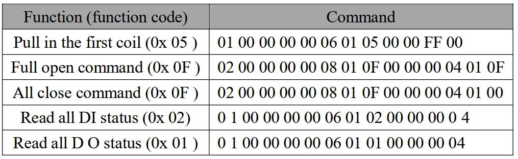
Modbus RTU control
the first D O output of M E3 1- AXAX4040 .

Other functions can be tested through the commands in the table below.

Technical Indicators
Specification and parameters

Device default parameters

Dimension

Ports and Indicators


Product function introduction
DI input
Switch input DI acquisition
The switch input DI measures level signals or edge pulse signals (rising edge, falling edge). Support dry node collection, support DI counting function, the maximum counting value is 65535 (counting beyond 65535 is automatically cleared).
The switch input DI supports three trigger modes: rising edge, falling edge, and level (default rising edge trigger).
The clearing method supports automatic clearing and manual clearing (automatic clearing by default).
Input filter
When the switch inputs DI to collect signals, it needs to maintain multiple sampling periods before confirming. Filter parameters can be set in the range of 1 to 16 (6 sampling periods by default, 6 *1 kHz ).
It can be configured with the host computer through instructions.
DO output
The output mode of the relay can output different mode outputs according to the mode set by the user, and the level output is turned on by default.
Input count
Support counting DI input , users can configure rising edge acquisition, falling edge acquisition, and level acquisition according to their own needs. You can also change the clearing method according to your needs.
Trigger method:
Rising edge: When the rising edge is collected (it is not counted when it is turned on, it is counted when it is turned off), it will be counted once.
Falling edge: When the falling edge is collected (counting when it is turned on, and not counting when it is released), count once.
Level: Two edges are collected and counted once respectively.
Clearing method:
Automatic: The device will automatically clear the DI count value register (0x 09DF ~ 0x 09E6 ) every time it is read.
Manual: Manual mode needs to write 1 to the clear signal register (0x 0AA7 ~ 0x 0AAE ), and each holding register controls one clear signal respectively.
Level output
Output according to the level set by the user, the switch characteristic of the level mode is similar to the function of a self-locking switch.
Pulse output
After the switch output DO is turned on, the switch output DO is automatically turned off after maintaining the set pulse width time (in ms). The pulse width setting range is 50~65535ms (the default is 50 ms ).
Follow mode
According to the following source configured by the user (when the device has AI acquisition or DI detection function, both DI or AI can be used as the following source, otherwise this function is useless) to change the relay state, multiple outputs can follow the same follow source output, simply put DI detects the input, and automatically outputs the relay that takes it as the following source (for example: DI is 1, DO is closed ). When the follow mode is turned on, the follow source should be configured at the same time, otherwise it will follow the first input by default.
Reverse follow mode
According to the following source configured by the user (when the device has AI acquisition or DI detection function, both DI or AI can be used as the following source, otherwise this function is useless) to change the relay state, multiple outputs can follow the same follow source output, simply put DI detects the input, and automatically outputs the relay as the following source (for example: DI is 1 , DO is disconnected ). When the follow mode is turned on, the follow source should be configured at the same time, otherwise it will follow the first input by default.
Trigger flip mode
According to the following source configured by the user (when the device has AI acquisition or DI detection function, both DI or AI can be used as the following source, otherwise this function is useless) to change the relay state, multiple outputs can follow the same follow source output, simply put When DI generates a trigger signal (rising edge or falling edge) , DO will have a state change . When the trigger flip mode is turned on , the following source should be configured at the same time, otherwise it will follow the first input by default.
Power-on state
According to the state set by the user. After the device is powered on, the output relay is turned on according to the state set by the user, and it is turned off by default.
Modbus gateway
The device can transparently transmit non-native Modbus commands from the network/serial port to the serial port/network, and the local Modbus commands are directly executed .
Modbus TCP/RTU protocol conversion
After opening, Modbus TCP data on the network side will be converted to Modbus RTU data .
Mod bus address filtering
This function can be used as the host to access the serial port of the device in some host software or configuration screen, and use the gateway function of the device, the slave is on the network end, and Modbus is turned on It is used when the function of TCP to RTU is converted. There are multiple slaves on the bus that may cause data confusion. At this time, enabling address filtering can ensure that only the specified address can pass through the device; when the parameter is 0, the data is transparently transmitted, and the parameter is 1-255 Only data from the set slave address is passed.
Mod bus TCP protocol data frame description
TCP frame format:

- Transaction ID: It can be understood as the serial number of the message. Generally, 1 is added after each communication to distinguish different communication data messages .
- Protocol identifier: 00 00 means Modbus TCP protocol.
- Length: Indicates the length of the next data in bytes.
Example: Get D I Status

Mod bus RTU protocol data frame description
RTU frame format:

Example: Get D I Status Command

IO linkage function
The linkage function is divided into A I-DO linkage and DI-DO linkage
Generally speaking, the linkage function needs to be divided into two parts.
The first part is the trigger source : both A I/DI input, the second part is the trigger: both DO/AO output
- When D I is used as the trigger source, the input state of D I and the change of D I can be used as signals, according to the corresponding configuration of D O
a. In follow/reverse follow mode, the current state of DI will be used as a signal, and the state of D O is the same/opposite to that of DI
b . Trigger inversion mode, DI state change is used as a signal, if the trigger signal is set to change on the rising edge of DI , then the current state of D O will change once - When AI is used as the trigger source, the AI signal is processed into a signal similar to DI through a process similar to Schmitt trigger , and then this signal is linked with DO . The linkage process can refer to DI /DO linkage .
Custom module information
Mod bus address
The device address is 1 by default, and the address can be modified, and the address range is 1-247.
Module name
Users can configure the device name according to their own needs to distinguish, support English, digital format, up to 20 bytes.
Network parameters
Unless otherwise specified: the following network-related parameters default to IPV4-related parameters.
- MAC of the device: the user can obtain it by reading the specified register, and this parameter cannot be written.
- IP address: device IP address, readable and writable.
- Mod bus TCP port : the port number of the device, readable and writable.
- Subnet mask : address mask, readable and writable.
- Gateway address: Gateway.
- DHCP : Set the way the device obtains IP : static (0), dynamic (1).
- Target IP: When the device works in client mode, the target IP or domain name of the device connection.
- Destination port: When the device is working in client mode, the destination port of the device connection.
- DNS server : The device is in the client mode and resolves the domain name of the server.
- Module working mode : switch the working mode of the module. Server: The device is equivalent to a server, waiting for the user’s client to connect, and the maximum number of connections is 4 . Client: The device actively connects to the target IP and port set by the user.
- Active upload: When this parameter is not 0, and the device is in the client mode, the discrete input status of the device will be uploaded to the server when it is connected for the first time or the input changes, and the analog input will be uploaded according to the configured time period.
Serial parameters
Parameters for setting serial communication:
Default parameters:
Baud rate: 9600 (03);
Data bit: 8bit;
stop bit: 1bit;
Parity digit: N ONE (00);
- Baud rate:

- check digit:

MODBUS parameter configuration
Note: According to the usage requirements, some software (such as KingView) requires adding +1 when converting from hexadecimal to decimal in order to operate on registers (all decimal values in the table have already been adjusted by +1).
D I register list

DO register list


Mod bus instruction operation example
1. Read Coil (D O ) Status
Use the read coil state (01 ) function code to read the output coil state, for example:

After sending the above command to the device through the 485 bus, the device will return the following values:

The above returned status data 0 1 indicates that the output DO 1 is turned on .
2. Control Coil (D O ) Status
Support operation of single coil (0 5 ), operation of multiple coils ( 0F ) function code operation.
Use the 0 5 command to write a single command, for example :
Use the 0 5 command to write a single command, for example :

After sending the above command to the device through the 485 bus, the device will return the following values:

The DO1 coil is turned on.
Use 0 F function code as the command to write multiple coils, for example:

After sending the above command to the device through the 485 bus, the device will return the following values:

The coils are all on.
3. read holding register
Use 03 function code to read one or more register values, for example:
Use 03 function code to read one or more register values, for example:

After sending the above command to the device through the 485 bus, the device will return the following values:

The above 00 00 means that DO1 is in level output mode .
4. Operation Holding Register
Support operation of single register (0 6 ), operation of multiple registers ( 10 ) function code operation.
Use 06 function code to write a single holding register, for example: set the working mode of DO1 to pulse mode

After sending the above command to the device through the 485 bus, the device will return the following values:

If the modification is successful, the data of the 0x0578 register is 0x0001, and the pulse output mode is turned on .
Use the 10 function code to write the command of multiple holding registers, for example: set the working mode of DO1 and DO2 at the same time.

After sending the above command to the device through the 485 bus, the device will return the following values:

If the modification is successful, the values of the two consecutive registers starting at 0x0578 are 0x0001 and 0x000 respectively. 1 marks DO1 and DO2 to enable pulse output .
Configuration Software
Acquisition and Control
Step 1: Connect the computer to the device
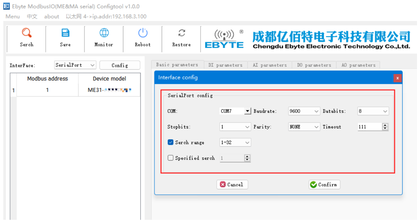
- You can configure the device by selecting the interface (serial port/network port); if you choose the network port, you must first select the network card and then search for the device.

- If you choose a serial port, you need to select the corresponding serial port number, and the same baud rate, data bit, stop bit, parity bit and address segment search range as the device, and then search
Step 2: Select the corresponding device

Step 3: Click the device online to enter the IO monitoring, the following is the IO monitoring screen display

Parameter setting
Step 1: For connecting devices, refer to “Acquisition and Control”
Step 2: User can configure device parameters, network parameters, DI parameters, AI parameters, DO parameters, and AO parameters (for example: if the device has no AO function, the AO parameters cannot be configured)


Step 3: After configuring the parameters, click Download Parameters, and you will see a prompt message in the log output that the parameters are saved successfully, click Restart the device, and the modified parameters will take effect after the device restarts.


The final interpretation right belongs to Chengdu Ebyte Electronic Technology Co., Ltd.
Revision history

About Us

Technical support: support@cdebyte.com
Documents and RF Setting download link: https://www.es-ebyte.com
Thank you for using Ebyte products! Please contact us with any questions or suggestions: info@cdebyte.com
————————————————————————————————-
Phone: +86 028-61399028
Web: https://www.es-ebyte.com
Address: B5 Mould Park, 199# Xiqu Ave, High-tech District, Sichuan, China
![]()
Copyright © 2012–2024 , Chengdu Ebyte Electronic Technology Co., Ltd.
Documents / Resources
 |
EBYTE ME31-AXAX4040 I/O Networking Module [pdf] User Manual ME31-AXAX4040 IO Networking Module, ME31-AXAX4040, IO Networking Module, Networking Module |