![]() +Quick Guide
+Quick Guide
your partner in sensor technology.
EE660 – Low Air Velocity Sensor with RS485 Interface
PLEASE NOTE
![]() Find this document and further product information on our website at www.epluse.com/ee660.
Find this document and further product information on our website at www.epluse.com/ee660.
Electrical Connection
![]() WARNING
WARNING
Incorrect installation, wiring or power supply may cause overheating and therefore personal injuries or damage to property.
For correct cabling of the device, always observe the presented wiring diagram for the product version used.
The manufacturer cannot be held responsible for personal injuries or damage to property as a result of incorrect handling, installation, wiring, power supply and maintenance of the device.
Hardware
The bus termination shall be realized with 120 Ω resistor using the switch on the electronics board.
NOTICE
Improper handling of the device may result in its damage.
- The power supply must be strong enough to ensure supply voltage within the specified range (see technical data) at any time and at all devices in the bus. This is particularly relevant when using long and thin cables as those can cause high voltage drop. Please note that a single EE660 requires peak current of 150 mA.
Wiring
Digital interface

Address Setting
Address Switch

Address setting via PCS10 Product Configuration Software
All DIP switches at position 0 → address has to be set via PCS10.
Modbus (slave device): factory setting 65 (permitted values: 1…247).
BACnet (master device): factory setting 65 (permitted values: 0…127).
Example: Address is set via configuration software = factory setting.
Address setting via DIP switch
Modbus (slave device): Setting the DIP switches to any other address than 0, overrules the Modbus address set via PCS10 (permitted values: 1…247).
BACnet (master device): Setting the DIP switches to any other address than 0, overrules the BACnet address set via configuration software.
BACnet Note: permitted values are 0…127. The 8th bit of the DIP switches is ignored.
(ID 127 = 0111 111). To set address 0 via DIP switches, the 8th bit shall be set to 1
(ID 0 = 1000 0000). Example: Address set to 11 (= 0000 1011 binary).\
BACnet Setup
Please refer to PICS (Product Implementation Conformance Statement), available on www.epluse.com/ee660.
Modbus Setup
FLOAT32
| Parameter | Unit 1) | Register number 2) [DEC] | Register address [HEX] 3) |
| Temperature | °C | 1003 | 3EA |
| Temperature | °F | 1005 | 3EC |
| Air velocity | m/s | 1041 | 410 |
| Air velocity | ft/min | 1043 | 412 |
INT16
| Parameter | Unit1) | Scale4) | Register number2) [DEC] | Register address3) [HEX] |
| Read register: function code 0x03 / 0x04 | ||||
| Temperature | °C | 100 | 4002 | FA1 |
| Temperature | °F | 50 | 4003 | FA2 |
| Air velocity | m/s | 100 | 4021 | FB4 |
| Air velocity | ft/min | 1 | 4022 | FB5 |
- The choice of measurement units (metric or non-metric) must be done according to the ordering guide, refer to EE660 datasheet.
- Switching from metric to non-metric or vice versa by using the PCS10 is not possible.
- Register number (decimal) starts from 1. 3) Register address (hexadecimal) starts from 0.
- Examples: For scale 100, the reading of 2550 means a value of 25.5. For scale 50, the reading of 2550 means a value of 51.
Communication settings (INT16)
| Parameter | Register number1) [Dec] | Register address2) [Hex] | Size3) |
| Write register: function code 0x06 | |||
| Modbus address4)5) | 1 | 00 | 1 |
| Modbus protocol settings4) | 2 | 01 | 1 |
Device information (INT16)
| Parameter | Register number1) [Dec] | Register address2) [Hex] | Size3) |
| Read register: function code 0x03 / 0x04 | |||
| Serial number (as ASCII) | 1 | 00 | 8 |
| Firmware version | 9 | 08 | 1 |
| Sensor name (as ASCII) | 10 | 09 | 8 |
- Register number starts from 1.
- Protocol address starts from 0.
- Number of registers.
- For Modbus address and protocol settings refer to Application Note Modbus AN0103 (available at www.epluse.com/ee660).
- If the ID is set via DIP-Switch the response will be NAK.
EE660 – Low Air Velocity Sensor with Analogue Output
Wiring
Voltage output 0-10 V
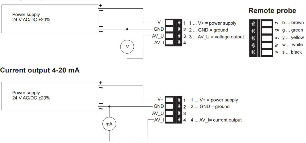
Jumper Settings
For performing the EE660 settings via the PCS10 Product Configuration Software (free download from www.epluse.com/pcs10) the jumper for the measuring range must be set to HI.
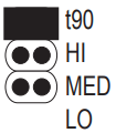
Selection of response time t LO 90
 |
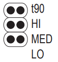 |
| Jumper t 90 SLOW 4 s (factory setting) | no jumper FAST 1 s |
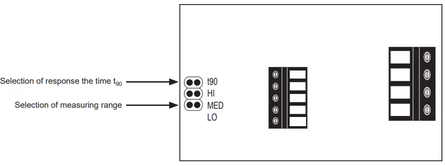
Selection of the measuring range
 |
 |
 |
| Jumper HI 0…2 m/s (0…400 ft/min) (factory setting) |
Jumper MED 0…1.5 m/s (0…300 ft/min) |
Jumper MED 0…1.5 m/s (0…300 ft/min) |
E+E Elektronik Ges.m.b.H.
Langwiesen 7
4209 Engerwitzdorf | Austria
T +43 7235 605-0
F +43 7235 605-8
info@epluse.com
www.epluse.com![]() QG_EE660 | Version v1.2 | 06-2024
QG_EE660 | Version v1.2 | 06-2024
All rights reserved | 302737
Documents / Resources
 |
E E Elektronik EE660 Low Air Velocity Sensor with Interface [pdf] User Guide EE660 Low Air Velocity Sensor with Interface, EE660, Low Air Velocity Sensor with Interface, Sensor with Interface, with Interface, Interface |