![]()
DTDS LoRa Module
User Manual
LoRa Module – DTDS-622C
FCC Compliance Statement (USA)
FCC ID: 2AXXTDTDS-622C-LORA
Compliance Statements:
This device complies with Part 15 of the FCC Rules. Operation is subject to the following two conditions:
- This device may not cause harmful interference.
- This device must accept any interference received, including, an interference that may cause undesired operation.
Caution Statements:
- Any changes or modifications not expressly approved by the party responsible for compliance could void the user’s authority to operate this equipment.
- This equipment should be installed and operated with a minimum distance of 20 cm between the radiator and your body.
This module is labeled with its own FCC ID. The end product using this module is required to display a label on itself referring to the enclosed module details. The final product must be labeled with the following: “Contains FCC ID: 2AXXTDTDS-622C-LORA”
The OEM using this product should not provide information to end-user regarding installation or removal of this transmitter RF module or information to change RF-related parameters in the user manual or by any means, with the end product.
The OEM shall integrate the module as per the module Integration guidelines and grant conditions.
The OEM is responsible for ensuring compliance with the applicable FCC rules for the transmitters operating individually and simultaneously.
Product Description
DTDS LoRa-622C is a low-cost, low power consumption long-range solution for wireless communication. The module complies with both Class A, B, and Class C LoRaWAN protocol specifications. It is suitable for Long Range sensor-based applications interfaced with an external host MCU. It also provides high interference immunity and meets all the LoRaWAN protocol specifications.
General Features
- Operating Temperature range -40 °C to +85 °C.
- AT Commands Interface over UART.
- Low power consumption.
- Assembly pads for easy PCB mounting.
- Highly compact Form Factor of 15 x 26 x 5 mm.
Applications
- Water Meters
- Energy Meters
- Home Automation
- Lighting Monitoring and Control
- Environmental Sensors
- Smart Cities
- Other IoT Products
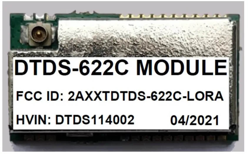
Package View
Figure 1- Top View of DTDS-622C Module
Pin I/O Description and Serial Configuration
| Pin Number | Pin Name | Pin Type | Pin Description |
| 1 | GND | Ground | |
| 2 | GND | Ground | |
| 3 | GND | – | Ground |
| 4 | GPIO/AN0 | I/O | Analog Input/GPIO |
| 5 | Reserved | Reserved for future use | |
| 6 | Reserved | Reserved for future use | |
| 7 | Reserved | Reserved for future use | |
| 8 | Reserved | – | Reserved for future use |
| 9 | NC | No Connection | |
| 10 | VDD MAIN | I | Supply for the Main Board |
| 11 | Reserved | Reserved for future use | |
| 12 | Reserved | – | Reserved for future use |
| 13 | NC | No Connection | |
| 14 | GND | Ground | |
| 15 | NC | No Connection | |
| 16 | UART_TxD | 0 | AT Commands Transmit to Host |
| 17 | UART_RxD | I | AT Commands Receive from Host |
| 18 | NC | – | No Connection |
| 19 | GPIO/AN3 | I/O | Analog Input/GPIO |
| 20 | GPIO/AN2 | I/O | Analog Input/GPIO |
| 21 | GPIO/AN1 | I/O | Analog Input/GPIO |
| 22 | VDD_RF | I | Supply for the RF Module |
| 23 | GND | – | Ground |
| 24 | GND | – | Ground |
| 25 | ANT | I/O | Antenna Signal |
| 26 | GND | Ground |
Table 1 – Pin Description for DTDS-622C Module
| Configuration Items | Value |
| Baud rate | 115200 bps |
| Data bit | 8 bits |
| Parity bit | None |
| Stop bit | 1 bit |
| Flow control | None |
| Local echo back | No |
| Line terminator | Transmission: CR+LF Reception: CR+LF |
Table 2 – Serial/ UART Configuration
Connection Circuit
Figure 2- Connection Diagram for User Application
Note: Antenna does not form the scope of supply with the module. An external antenna can be connected to the UFL connector available on the module or the Antenna output from the module can be extended to an SMA or any other type of connector on the host application board. The recommended Antenna is 50 Ohms terminated Taoglas T1.92.2113 Omnidirectional Antenna with a peak gain not exceeding 2.14 dB in the bent configuration.
Technical Specifications
| Parameters | Typical Specifications | Units | |
| Mechanical Specification | Size | 15(W) X 27(L) X 5(H) | mm |
| Package | 26 pins, SMD | – | |
| Electrical Specification | Power Supply | 3 — 3.7, 3.3 Typical | V |
| Standby Current | < 4 | mA | |
| Sleep Current | :-.15 | 11A | |
| TX Current | 138@BW 125 KHz, 22 dBm, 865/868/915/923 MHz | mA | |
| RX Current | 8@ BW 125 KHz, 22 dBm, 865/868/915/923 MHz | mA | |
| Data Rate | 0.018 to 62.5 (LoRa) | Kb/s | |
| RF Interface | RHO single-ended, 50 Ohm | ||
| Operating Frequency Bands | EU 868 | MHz | |
| US 915 | MHz | ||
| AS 923 | MHz | ||
| IN 865 | MHz | ||
| RF Specification | Sensitivity | -137d8m @SF12, BW 125kHz | dBm |
| -124d8m @SF7, BW 125kHz | |||
| RF interface | RFIO | – | |
| Interfaces | USART | USART_TX, USART_RX | – |
| 12C | 12C_SCL,12C_SDA | – | |
| Host interface available via AT commands over UART | – |
Table 3-Electrical, Mechanical and LoRaWAN specifications of DTDS-622C Module
Physical Dimensions
Figure 3- Physical Dimensions of the DTDS-622C Module (all units are in mm)
Revision History
| Rev | Date | Description Section | Summary |
| 1.0 | Mar 12, 2021 | – | Initial Release |
| 1.1 | Apr 19, 2021 | Contents | Added FCC compliance statements |
Documents / Resources
 |
DTDS 622C LoRa Module [pdf] User Manual DTDS-622C-LORA, DTDS622CLORA, 2AXXTDTDS-622C-LORA, 2AXXTDTDS622CLORA, LoRa-622C Low Cost Low Power Consumption Long Range Solution, 622C LoRa Module, 622C, LoRa Module |


