DOD R410 MK II PA Processor Rack
CAUTION

The symbols shown above are internationally accepted symbols that warn of potential hazards with electrical products. The lightning flash with arrowpoint in an equilateral triangle means that there are dangerous voltages present within the unit. The exclamation point in an equilateral triangle indicates that it is necessary for the user to refer to the owner’s manual.
These symbols warn that there are no user serviceable parts inside the unit. Do not open the unit. Do not attempt to service the unit yourself. Refer all servicing to qualified personnel. Opening the chassis for any reason will void the manufac-turer’s warranty. Do not get the unit wet. If liquid is spilled on the unit, shut it off immediately and take it to a dealer for service. Disconnect the unit during storms to prevent damage.
U.K. MAINS PLUG WARNING
A moulded mains plug that has been cut off from the cord is unsafe. Discard the mains plug at a suitable disposal facility. NEVER UNDER ANY CIRCUMSTANCES SHOULD YOU INSERT A DAMAGED OR CUT MAINS PLUG INTO A 13 AMP POWER SOCKET. Do not use the mains plug without the fuse cover in place. Replacement fuse covers can be obtained from your local retailer. Replacement fuses are 13 amps and MUST be ASTA approved to BS1362.
SAFETY INSTRUCTIONS
(EUROPEAN)
- NOTICE FOR CUSTOMERS IF YOUR UNIT IS EQUIPPED WITH A POWER CORD.
- WARNING: THIS APPLIANCE MUST BE EARTHED.
- The cores in the mains lead are colored in accordance with the following code:
- GREEN and YELLOW – Earth BLUE – Neutral BROWN – Live
- As colors of the cores in the mains lead of this appliance may not correspond with the colored markings identifying the terminals in your plug, proceed as follows:
- The core which is colored green and yellow must be connected to the ter-minal in the plug marked with the letter E, or with the earth symbol, or col-ored green, or green and yellow.
- The core which is colored blue must be connected to the terminal marked N or colored black.
- The core which is colored brown must be connected to the terminal marked L or colored red.
- These units comply with the European “EMC Directive” for emissions and suscept-ability.
- The power cord is terminated in a CEE7/7 plug (Continental Europe). The green/yellow wire is connected directly to the unit’s chassis. If you need to change the plug, and if you are qualified to do so, refer to the table below.

- WARNING: If the ground is defeated, certain fault conditions in the unit or in the system to which it is connected can result in full line voltage between chassis and earth ground. Severe injury or death can then result if the chassis and earth ground are touched simultaneously.
IMPORTANT!
FOR YOUR PROTECTION, PLEASE READ THE FOLLOWING:
- WATER AND MOISTURE: Appliance should not be used near water (e.g. near a bathtub, washbowl, kitchen sink, laundry tub, in a wet basement, or near a swim-ming pool, etc). Care should be taken so that objects do not fall and liquids are not spilled into the enclosure through openings.
- POWER SOURCES: The appliance should be connected to a power supply only of the type described in the operating instructions or as marked on the appliance.
- GROUNDING OR POLARIZATION: Precautions should be taken so that the grounding or polarization means of an appliance is not defeated.
- POWER CORD PROTECTION: Power supply cords should be routed so that they are not likely to be walked on or pinched by items placed upon or against them, paying particular attention to cords at plugs, convenience receptacles, and the point where they exit from the appliance.
- SERVICING: The user should not attempt to service the appliance beyond that described in the operating instructions. All other servicing should be referred to qualified service personnel.
INTRODUCTION
Congratulations, and thank you for your purchase of the 410 Series II P.A./Monitor Processor. This monitor/speaker processor is to be used in conjunction with a sound reinforcement system, or can serve as the final EQ and level control for the monitor system.
The 2/3rds octave EQ allows you to quickly and easily modify a sound for use in music, recording, or sound reinforcement. The notch filters give you more control over notching out unwanted noise and the limiting and low cut features assist in protecting your amps and speakers.
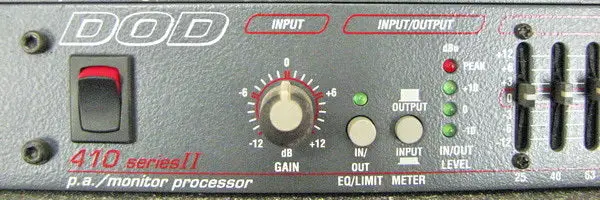
Front Panel

- Power Switch – Applies power to the 410.
- Input Gain Stage – Controls the level of the input signal.±12dB adjustment.
- Input/Output Section – The EQ/Limit switch, switches in or out the graphic EQ, notch filters, and the limiter. This allows a comparison of the signal “wet” or “dry”. The input level and low-cut filter are always in the signal path regardless of the switch position. The meter switch connects the LED level meter to the input (post-input level) or the output.
- Graphic EQ – This is a 15 band, 2/3rds octave graphic EQ. It provides ±12dB of gain for each band. The peak LED indicates that.The signal out of the EQ section is 3dB below clipping.
- Notch Filters – These two filters are very narrow bandwidth notch filters that can provide 24dB of attenuation at the select-ed frequency. The x10 function allows you to change the range of each notch (see the graph below). These filters are “Disabled” by setting the depth control to the top (0dB cut). These filters are used primarily for eliminating feedback or hum from the P.A. or monitor systems.

- Limiter – The limiter function features Automatic Variable Ratio Limiting™. AVR Limiting behaves as a mild compressor with a soft knee at low threshold settings, and a hard knee lim-iter at higher threshold settings. This allows the limiter to func-tion as a mild compressor or as a limiter for speaker protection. The fast/slow speed switch affects both the attack and release time. This gives enough variety for most situations. The gain reduction meter displays the amount of gain reduction due to limiting.
- Low Cut – A selectable low cut (high pass) filter that may be switched in or out and has selectable rolloff frequency of 40 or 80Hz.
Rear Panel

- Balanced Output -Accepts a female XLR plug (see section on installation for wiring). Maximum balanced output level is 21dBu. Output impedance is 102Ω balanced.
- Balanced/Unbalanced Output – Accepts a 1/4” tip-ring-sleeve balanced or 1/4” unbalanced tip-sleeve plug (see section on installation for wiring connections). Maximum output level is 21dBu. Output impedance is 20kΩ for the unbalanced con-nection and 40kΩ for balanced.
- Balanced Thru Output – Accepts a female XLR plug (see section on installation for wiring connections). This output is hardwired to the input allowing the signal to be split off to another destination. Balanced output is possible only with a balanced input signal.
- Balanced/Unbalanced Thru Output – Accepts a 1/4” tip-ring-sleeve balanced phone plug or a 1/4” unbalanced tip-sleeve plug (see section on installation for wiring connections).
- Balanced Input – Accepts a male XLR plug (see section on installation for wiring connections). Maximum allowable input is 21dBu. Input impedance for the balanced connection is
102Ω. - Balanced/Unbalanced Input – Accepts a 1/4” tip-ring-sleeve balanced phone plug or a 1/4” unbalanced tip-sleeve plug (see section on installation for wiring connections). Maximum allowable input is 21dBu . Input impedance is 51Ω for the unbalanced connection and 102Ω for balanced .
INSTALLATION
Install the 410 in a rack with the provided rack screws. Route the AC power cord to a convenient power outlet away from audio lines.
Connections to the input and output jacks are made using 1/4” balanced tip-ring-sleeve (TRS) plugs, or 1/4” unbalanced tip-sleeve (TS) plugs, or balanced XLR plugs.

Once the 410 has been installed and adjusted, an optional 801 security panel may be installed to keep unauthorized persons from tampering with the settings.
APPLICATIONS
- A. Using the 410 in conjunction with a real time analyzer (such as DOD’s RTA Series II), a calibrated microphone, and pink noise generator, the audio system may be tuned to make the overall audio spectrum response of the sound system and the room environment flatter in frequency response.
- B. Greater gain-before-feedback characteristics may be achieved by turning up the sound system to the feedback point and attenuating the oscillating (ringing) frequency using the notch filters. Turn the system up to feedback again and attenuate the second oscillating frequency using the second notch filter.
- C. Limiting sets the maximum allowable output level as set by the threshold control. Limiting prevents clipping in amps and protects your speakers.
- D. Protection of amplifiers and speakers may be accomplished using the LOW CUT feature of the equalizer. Wind noise or dropped microphones can cause damage to the amps and /or speakers. However, by rolling off the extreme low frequencies, a measure of protection is added to the system without severely affecting the overall sound quality.
- E. In noisy environments, the audio signal may be tailored for better intelligibility and penetration. This is particularly useful for public address systems.
- F. Creative use of the equalizer allows shaping of the signal for a more pleasing sound or for special effects. The only limits are those of taste and imagination.
Stage monitor processor application:

House P.A. application:

Permanent installation multi-room application:

Maintenance and Service
- Other than keeping the unit clean and occasionally checking the connectors and cables to the unit for integrity, there is no main-tenance necessary for the DOD 410 P.A./Monitor Processor.
- There are NO user serviceable parts inside the unit. Opening the chassis will void the warranty. All service and repair must be performed by the factory for the warranty to remain in ser-vice.
- Should a problem arise with the product, please contact your authorized DOD Electronics dealer for return/repair procedures.
DOD Warranty
- The warranty registration card must be mailed within ten days after the purchase date to validate this warranty.
- DOD warrants this product, when used solely within the U.S., to be free from defects in material and workmanship under nor-mal use and service.
- DOD Electronics liability under this warranty is limited to repairing or replacing defective materials that show evidence of defect, provided the product is returned through the original dealer, where all parts and labor will be covered up to a period of one year.
- The company shall not be responsible for any con-sequential damage as a result of the products use in any circuit or assembly.
- Proof of date of purchase is considered to be the burden of the consumer.
- DOD reserves the right to make changes in design or make improvements upon this product without incurring any obligation to install the same on PRODUCTS PREVIOUSLY MANUFACTURED.
- The foregoing is in lieu of all other warranties, either expressed or implied, and DOD neither assumes nor authorizes any person to assume for it any obligation or liability in connection with the sale of this product. In no event shall DOD or its dealers be liable for special or consequential damages or form any delay in the performance of this warranty due to causes beyond their control.
Specifications
- Frequency Response: 10Hz – 30kHz, ±0.5dB.
- THD + Noise: < 0.04% @ 1kHz.
- Signal to Noise Ratio: Better than 97dB.
- Input Impedance: 20kΩ unbalanced, 40kΩ balanced.
- Maximum Input Level: +21dBu (ref; 0.775 VRMS).
- Output Impedance: 51Ω unbalanced, 102Ω bal-anced.
- Maximum Output Level: ±21dBu.
- Thru Output: Hard-wired to input.
- Graphic EQ Band Separation: 2/3 Octave. Notch Filter Q: > 40.
- Limiter Attack Time: Slow 18ms, Fast 2ms.
- Limiter Release Time: Slow 180ms, Fast 20ms.
- Low Cut Filter Slope: 12dB/Octave.
DOD ELECTRONICS CORPORATION 8760 SOUTH SANDY PARKWAY SANDY, UTAH 84107
INTERNATIONAL DISTRIBUTION 3 OVERLOOK DR. UNIT 4 AMHERST, NEW HAMPSHIRE 03031 U.S.A.
FAX 603-672-4246
DOD IS A REGISTERED TRADEMARK OF DOD ELECTRONICS
© 1995 DOD ELECTRONICS CORPORATION
PRINTED IN U.S.A. 7/95 MANUFACTURED IN THE U.S.A. DOD 410 18-2101-B
Frequently Asked Questions
Q: Can I open the unit for servicing myself?
A: No, it is recommended to refer all servicing to qualified personnel to avoid the risk of electric shock.
Q: What should I do if liquid is spilled on the unit?
A: Immediately shut off the unit and take it to a dealer for professional service.
Q: How should I handle the power cord?
A: Ensure the green/yellow wire is connected to the unit's chassis and follow the provided wire color codes when changing plugs.
Documents / Resources
 |
DOD R410 MK II PA Processor Rack [pdf] User Guide R410, R410 MK II PA Processor Rack, R410, MK II PA Processor Rack, Processor Rack, Rack |