![]() Installation Guide
Installation Guide
Remote Control Unit
PVRE Serie 2 15 7 R9954
PVRE Series 2 Remote Control Unit
| Code 162F…. | 1310 (1300) |
1311 (1301) |
1312 (1302) |
1313 (1303) |
1314 (1304) |
| Symbol | |||||
| Prop 1 | x | x | x | x | x |
| Prop 2 | x | x | x | ||
| Prop 3 | x | ||||
| ON/OFF | x | x |
Lead colours and electrical diagram
The numbers in [ ] refer to the terminal numbers in the SUB-D connector of the joystick.
The indicated colours refer to the colours of the leads in Danfoss’ accessory cable.

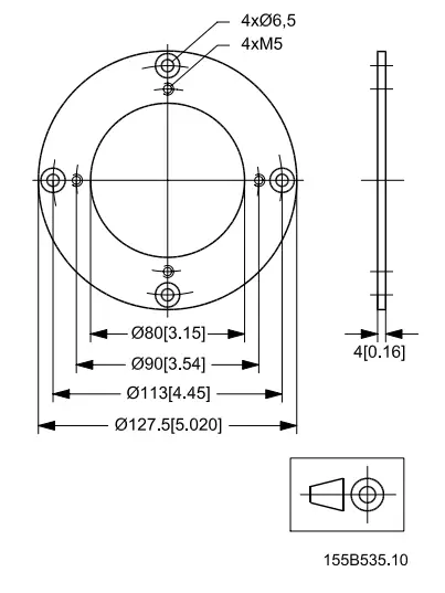
Dimensions

Positioning of grip
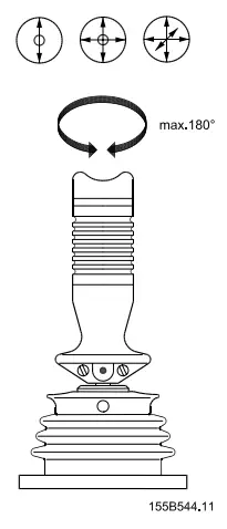
| Across fats | Torque | |
| H1 | 2,5 | 2,1 ± 0,1 Nm |
| H2 | 2,5 | 2,1 ± 0,1 Nm |
Electrical system

Accessories
Cable: SUB-D for tabs A 6,3 – 0,8*
Connector,
Color code/connector,
 Adapter ring: Installation as PVRE series 1.
520L0281
Rev BB
Mar 2014
© Danfoss, 2014-03
Documents / Resources
 |
Danfoss PVRE Series 2 Remote Control Unit [pdf] Installation Guide 162F...., 162B6017, 162B4100, PVRE Series 2 Remote Control Unit, PVRE Series 2, PVRE Series 2 Remote, Remote Control Unit, Remote Control, Control Unit, Control, Remote |