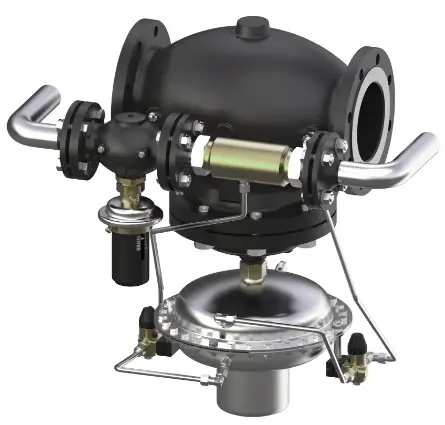
Danfoss DN 100- DN 250 Pilot Controlled Flow Rate and Differential Pressure Controller
Specifications
- Product Name: Pilot-controlled Flow Rate and Differential Pressure Controller PCVPQ
- Model: VI.JA.H3.5B
- Sizes: DN 100 – DN 250
- Pressure Ratings: PN 16 / PN 25
Product Usage Instructions
Safety Notes
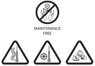
The product is maintenance-free. Assembly, start-up, and maintenance should only be carried out by qualified personnel. Ensure the system is depressurized, cooled down, emptied, and cleaned before any work.
Description
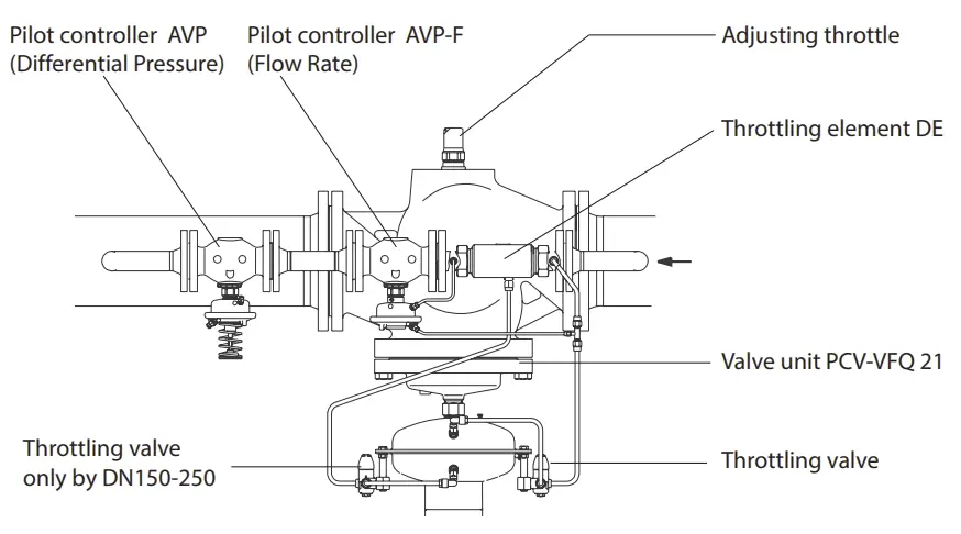
The PCVPQ is a pilot-controlled flow rate and differential pressure controller. It consists of pilot controllers AVP and AVP-F for differential pressure and flow rate adjustments respectively, along with an adjusting throttle element DE.
Mode of Operation
Differential Pressure Control: The valve remains closed at low flow rates through a pressure spring. If the flow rate reaches the setpoint, differential pressure increases, closing the valve to restrict flow rate.
Scope of Delivery
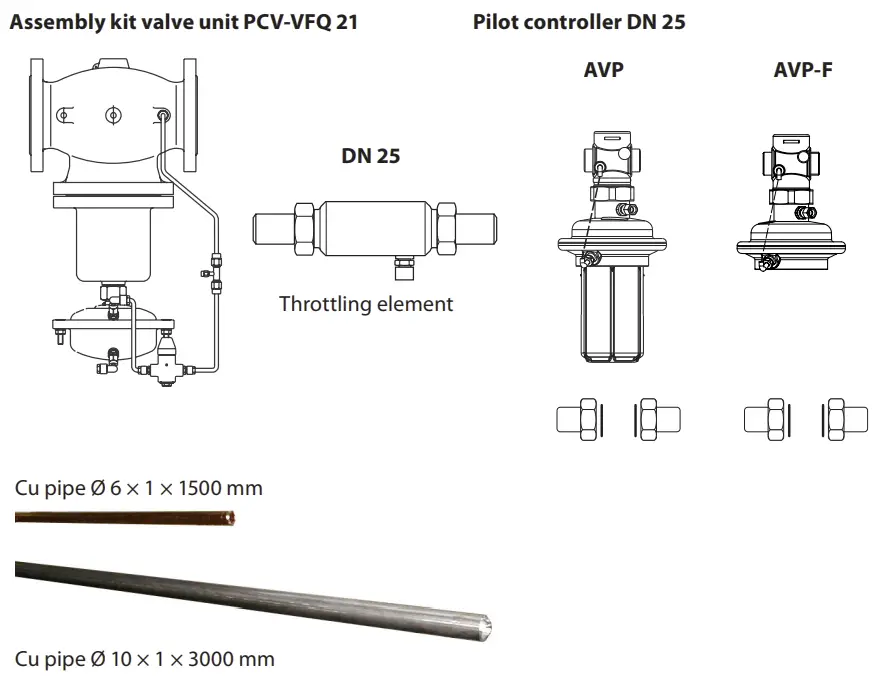
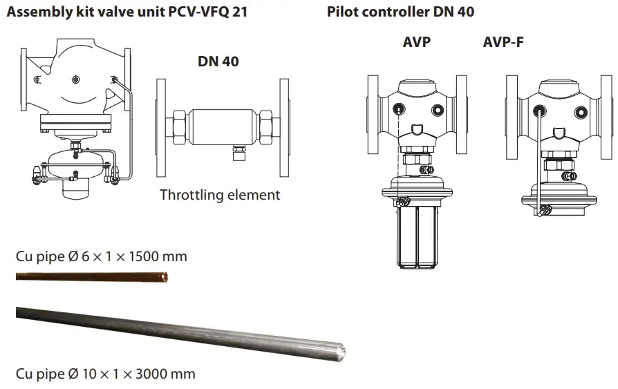
Each PCVPQ assembly kit includes components based on sizes:
- DN 100-125: Assembly kit valve unit PCV-VFQ 21, Pilot controller DN 25 AVP, Throttling element
- DN 150-250: Assembly kit valve unit PCV-VFQ 21 DN 40, Pilot controller DN 40 AVP AVP-F
Assembly
Prior to Assembly:
Ensure the system is depressurized before starting any assembly work.
Installation Position, Installation Place:
Take care to correctly position the cutting rings during installation.
Impulse Tube Installation:
Follow the instructions for installing impulse tubes correctly.
Insulation:
Do not insulate the diaphragm actuators when insulating system parts. Do NOT weld the actuators.
Instructions
Safety Notes
- Prior to assembly and commissioning to avoid injury of persons and damages of the devices, it is absolutely necessary to carefully read and observe these instructions.
- Necessary assembly, start-up, and maintenance work must be performed only by qualified, trained and authorized personnel.
Prior to assembly and maintenance work on the controller, the system must be:
- depressurized, cooled down, emptied and cleaned.
Please comply with the instructions of the system manufacturer or system operator.
Definition of Application
- The controller is used for flow rate limitation of water for heating, district heating and cooling systems.
- The admissible medium temperatures depend on the design and comprise 5-150 °C, 5-200 °C.
- The technical data on the rating plates deter-mine the use.
Description
Construction
Mode of Operation
- The control unit consists of the PCV-VFQ21 valve unit, installed in the main pipe, and the differential pressure controllers AVP and AVP-F installed as pilot controllers in the bypass. In the bypass line, a throttle element is installed in front of the pilot controllers.
- The controller keeps the differential pressure for the corresponding section on a constant level and restricts the flow rate to the adjusted setpoints.
- The valve and the pilot valves are pressure-balanced.
- The setpoint for the differential pressure is adjusted by pre-stressing the setpoint spring of the pilot controller AVP. The setpoint for the flow rate limitation is adjusted at the adjusting throttle of the valve unit.
- The valve unit in the main pipe is opening on rising pressure. The pilot controllers in the bypass line are closing on rising pressure.
Differential Pressure Control
- In case of small flow rates, the valve in the main pipe remains closed through the pressure spring in the actuator of the valve unit. The pressure is exclusively controlled by the pilot controller.
- If the flow rate in the bypass is increased, the pressure in the throttle element (Venturi nozzle) decreases.
- The reduced pressure acts through an impulse tube upon the lower chamber of the actuator of the valve unit. The main valve is thus opened shock-free and continuously.
- If the flow rate is reduced, the pressure in the throttle element raises and the main valve closes. This sequential switching guarantees an operation free of vibrations and a small control deviation over a wide positioning range.
Flow Rate Limitation
- If the flow rate reaches the adjusted setpoint, the differential pressure increases at the adjusting throttle. This differential pressure acts on the actuator AVP-F via the impulse tubes and the valve AVP-F closes. Consequently, the valve of the valve unit is throttled, too, and the flow rate is restricted.
Technical Data
Technical data, see rating plates and the PCV data sheet.
Scope of Delivery
DN 100-125
DN 150-250
Assembly
Prior to Assembly:
- Depressurized system before any assembly work !
CAUTION!
- Clean pipeline system.
- Install strainer in front of the controller.
- Install shut-off units in front of and behind the controller.
Installation Position, Installation Place
- Installation is only permitted in horizontal pipelines with the actuators hanging in a downward position.
- The controller may be installed in the supply as well as in the return line.
When installing:
- Observe direction of flow.
- Design with welded ends:

- Loads on the valve body and the throttle element by the pipes are not permitted.
Impulse Tube Installation
See installation scheme, section 6.6.
For CU pipes Ø 10 × 1, insert sockets 1 on both sides.

Care for correct position of the cutting rings 2.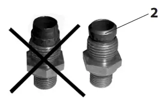
Insulation
The diaphragm actuators must not be insulated when insulating system parts.
Installation Scheme


Assembly Drawings, Dimensions

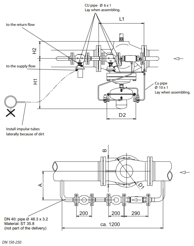
Dimensions
| Nominal diameter DN | 100 | 125 | 150 | 200 | 250 | |
| L1 |
mm |
350 | 400 | 480 | 600 | 730 |
| H1 | 530 | 530 | 619 | 647 | 697 | |
| H2 | – | 245 | 300 | 325 | ||
| D2 | 263 | 380 | ||||
| D1 | 150 | 250 | 320 | 385 | 500 | |
| B | 200 | 210 | 310 | 336 | 412 | |
| A ≥ | 290 | 320 | 350 | 410 | ||
Start-up
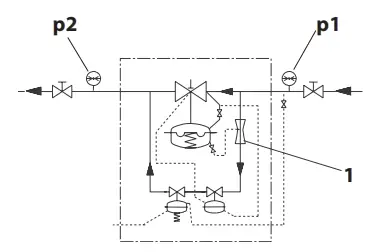
Required Static Pressure, Pressure Difference
- For a proper functioning, a minimum pressure difference of p1 – p2 ≥ 0.5 bar is required.
- The static pressure p1 in front of the controller must not fall below 1.5 bar (excess pressure). Nonobservance may lead to cavitation and damages in the throttling element 1.
Leak and Pressure Tests
To avoid too high pressures at the diaphragm actuators, the following should be observed prior to any pressure tests:
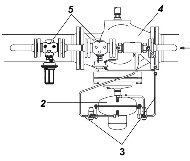
Actuator of valve unit:
The admissible operating excess pressure in the actuator 2 is 25 bar 1). For higher pressures, you must:
- Remove the impulse tubes 3 at the actuator and close the connections with a stopper.
- Prior to any leak or pressure test, the instructions in section 7.3 must be complied with.
- Pre-condition: Same pressure on both sides of the diaphragm.
Filling the System
Note:
- The controller 4 is closed when no pressure is applied and only opens with a defined flow in the bypass.
- The pilot controller 5 is closing on rising pressure.
To avoid too high pressure differences on the controller, observe the following sequence when starting-up !
This procedure guarantees that there is no overturn of the diaphragm in the valve and the actuators.
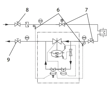
- Open shut-off valves 6 that possibly exist in the impulse tubes.
- Open units 7 of the system.
- Slowly open shut-off units in the supply flow 8 and the return flow 9.
 Start-up
During starting-up the filled system, open the units in the same sequence as described in section 7.3.
Putting out of operation
When putting the system out of operation, first close the shut-off units in the supply flow and then those of the return flow.
Flow Rate Adjustment
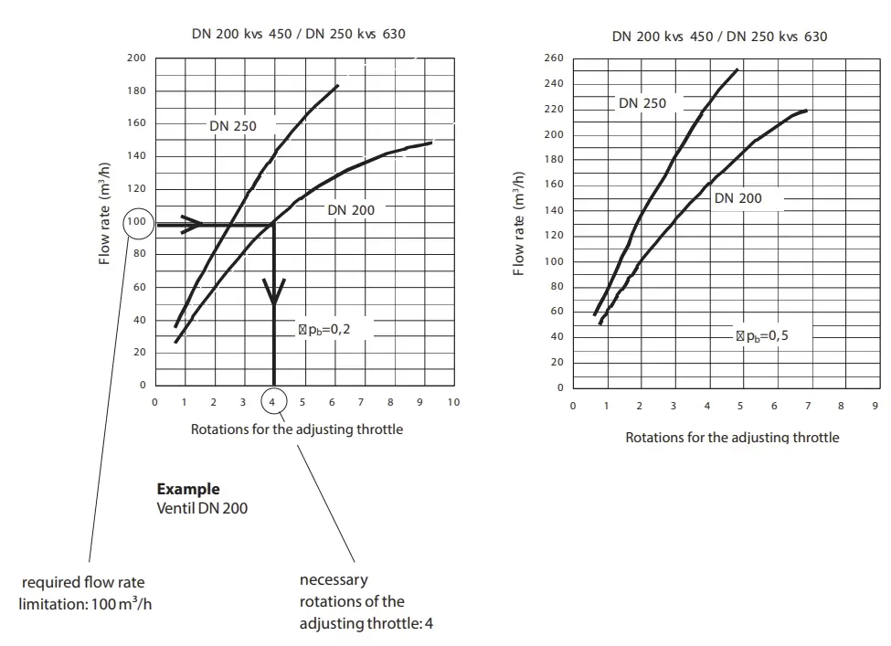
- The setting of the setpoint for the flow rate limitation is made by means of flow adjusting curves (see section 7.7) or a heat meter (see page 33).
Adjustment by means of flow adjusting curves
- Adjustment is to be made at a shut-down system.
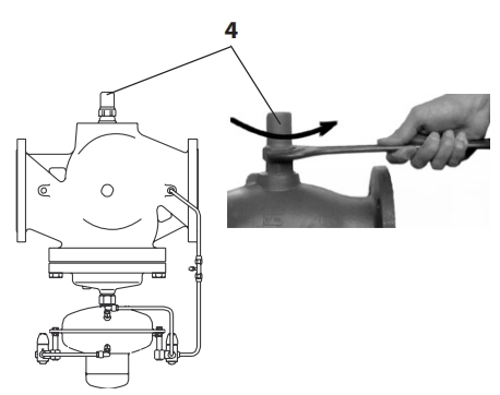
Procedure
- Unscrew cover 1.

- Loosen the counter nut 2.

- Screw in the adjusting throttle 3 to its stop.

- Screw in the adjusting throttle 3 to its stop.
- Choose diagram, (see section 7.7, Flow Adjusting Curves) Observe effecitve pressure ∆pb: 0.2 or 0.5 bar see rating plate on the actuator AVP-F
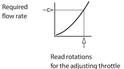
- Turn the adjusting throttle by this number of rotations to the left.

- The adjusted flow rate can be verified by means of a flow rate measuring device. Perhaps you need to re-adjust the flow rate. Care for an adequate differential pressure in the system.
- Tighten the counter nut without changing the position of the adjusting throttle.

- Re-screw the cap nut 1.
- The cap nut can be sealed.
 The flow rate adjustment is completed. Now, adjust the differential pressure, see section 7.8.
Start-up
Flow Adjusting Curves

Adjustment by means of a flow rate measuring device:
Procedure
- Prior to the adjustment of the flow rate, start the system in accordance with the instructions given in section 7.4.
- The shut-off units 1 and the control units 2 must be completely opened so that the flow rate is not restricted by a unit.
The adjustment can also be carried out via a bypass 3.
- Unscrew cap nut 4.
- Loosen the counter nut 5.

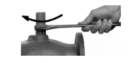
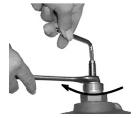
- Adjust the flow rate limitation by turning the adjusting throttle 6:
Turning to the right 7, reduces the flow rate. Turning to the left 8, increases the flow rate.
- Observe the flow rate indicator.
- After having completed the adjustment, tighten the counter nut without changing the position of the adjusting throttle.
- Re-screw the cap nut.

- The cap nut can be sealed.The flow rate adjustment is completed.
Adjustment of the Differential Pressure
The setpoint of the differential pressure must be adjusted at the pilot controller AVP 1. The etpoint range is indicated on the rating plate of the actuator.

Procedure
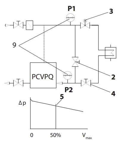
- Prior to the differential pressure adjustment, start the system as described in section 7.4. The differential pressure can also be adjusted while the bypass 2 is opened.
- Adjust the flow rate at the unit by which the differential pressure is controlled. Adjustment, e.g. at unit 3 or 4 or via bypass 2 to approx. 50 % of the max. flow rate 5.
- Turning to the right, increases the setpoint.
 Turning to the left, reduces the setpoint.
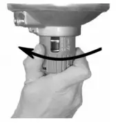
- Observe pressure indicators 9.
- After having completed the differential pressure adjustment, check at the open system whether the max. flow rate is reached. If not, increase the differential pressure.
Sealing
The setpoint adjusters may be sealed.
Adjustment of the Throttle Valves
Number of throttle valves:
- DN 100, 125: 1 ×
- DN 150-250 : 2 ×
- Unscrew cover 1.

- Standard adjustment:
Turn in the valve spindle by turning it to the right by means of a wrench SW5 to its stop. Then unscrew valve spindle by turning it to the left by approx. 10 rotations. - Increase of damping, e.g. necessary in case of pressure vibrations.
Screw in the valve spindle by turning it to the right. - Reduction of damping, e.g. in case of a control that is too slug.
Unscrew the valve spindle by turning it to the left.
Function Test
Differential pressure
- Check the differential pressure on the pressure indicators by opening and closing a unit in the corresponding section of the system to be controlled.
- If the differential pressure is vibrating, slightly close the throttle valves (see section 7.9).
- If the differential pressure is exceeded in either direction, adjust the differential pressure as described in section 7.7.
Flow rate
- The adjusted flow rate must not be exceeded if the system is completely open.
- If the setting is exceeded in either direction, check the adjustment as described in section 7.5.
Trouble Shooting
| Fault | Possible cause | Remedy | |
|
Controller does not hold the flow rate or differential pressure on a constant level |
Throttle valve is open too widely. | Slightly close the throttle valve, see section 7.10. | |
|
Air in the actuators |
1.
2.
3. |
Loosen impulse tube connections at the actuators by approx. 1 rotation.
Deaerate, Caution hot water ! (move impulse tube until medium penetrates). Tighten impulse tube connections. |
|
| Impulse tubes or impulse tube connections are dirty or damaged. | 1.
2. |
Remove impulse tube.
Clean impulse tubes and impulse tube connections and check for free passage. |
|
|
Differential pressure is too high |
Pilot valve AVP, AVP-F does not close: Valve seat or plug is dirty or damaged. |
1.
2.
3. 4. |
Remove impulse tube. Dismount actutor and trim. Procedure see section 9.4. Clean seat and plug.
If damaged, replace trim or valve. |
|
Valve VFQ 2 does not close: Valve seat or plug is dirty or damaged. |
1.
2.
3. 4. |
Remove impulse tube. Dismount actutor and trim 1). Procedure, see section 9.2. Clean seat and plug.
If damaged, replace trim or valve. |
|
| Rolling diaphragm in the actuator AVP, AVP-F (pilot controller) is defective, i.e. valve AVP does
not close. |
1.
2. |
Remove impulse tube.
Replace actuator, see section 9.3. |
|
|
Differential pressure or flow rate is too low |
Valve plug of the pilot valve AVP does not open: Valve seat or plug is dirty or damaged, trim is dirty. |
1.
2.
3. 4. |
Remove impulse tube. Dismount actuator and trim. Procedure, see section 9.4. Clean seat and plug.
If damaged, replace trim or valve. |
| Valve plug of the pilot valve VFQ 21 does not open:
Valve seat or plug is dirty or damaged, trim is dirty. |
1.
2.
3. 4. |
Remove impulse tube. Dismount actutor and trim 1).
Procedure, see sections 9.1 and 9.2. Clean seat and plug. If damaged, replace trim or valve. |
|
|
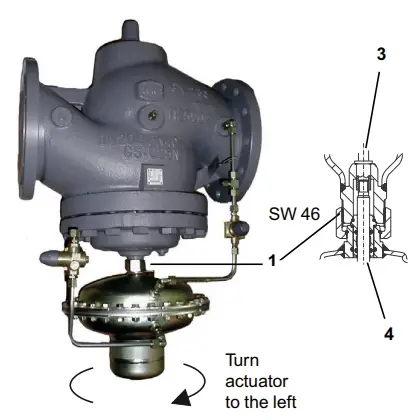
Rolling diaphragm in the actuator of the valve unit is defective, i.e. valve VFQ 21 does not open. |
1.
2.
3. |
Remove impulse tube.
Loosen union nut SW 46 and remove actuator, see also section 9.1. Replace actuator. |
|
- The trim can be replaced by qualified personnel up to DN 125.
- From DN 150 replacement should be carried out by the Danfoss service personnel.
Replacement of Valve, Actuator, Trims
Dismounting and Mounting Actuator and Valve
Note:
The springs 1 in the actuator are pre-stressed. Therefore, the actuator must be pushed upwards to be dismounted. You need a second person to do this.
Valve unit DN 100–125
 Valve stem 3 and the stem of the actuator 4 are not screwed to eachother.
Dismounting
- Dismount impulse tubes.
- Support actuator below or by a second person as the springs 1 are pre-stressed.
- Loosen union nut 2.
- Remove actuator.
Prior to assembly check cone 5 !

- Clean cone prior to mounting.
- Check O rings for damages, in case of damages, replace cone (see Spare Parts).
- Grease cone with high-performance fitting component: BARRIERTA L55/3 HV (see Spare Parts).
Mounting
- Place actuator at the valve and push upwards.
- Screw on union nut 2.
- Align actuator, observe position of impulse tube connections.
- Tighten union nut 1, max. torque 100 Nm.
Valve unit DN 150–250
 The stem of the actuator 4 is screwed into the valve stem 3.
Dismounting
- Dismount impulse tubes.
- Completely loosen union nut 1.
The actuator hangs on the screwed-in stem 4.
The actuator weights approx. 20 kg. In addition, an internal spring package is pre-stressed. Secure against dropping down before unscrewing. - Screw the stem of the actuators 4 out of the valve stem 3 by turning the actuator to the left.
Mounting
- Place actuator at the valve and push upward to press the spring package in the actuator together (second person necessary).
- Carefully turn actuator to the right.
By this, carefully screw in the stem of the actuator into the valve stem to its stop.
Then, return the actuator by approx. 1 rotation (to the left) - Align actuator, observe position of the control lines connections.
- Tighten union nut 1, torque 100 Nm.
Replacement of Trim Valve VFQ 21
The trim can be replaced by qualified personnel up to DN 125. From DN 150 replacement should be carried out by the Danfoss service personnel.
Removing the trim: Valves DN 100–125

- Dismount actuator 1 (see section 9.1).
- Unscrew hexagon head cap screw 2.
- Remove bonnet 3.
- Take out trim 4.
Prior to installation:
Clean sealing surfaces 5 and socket 6, grease sealing surfaces with antiseize graphite petroleum.

Installing the trim:
Mounitng is carried out in reverse order. Torque hexagon head cap screws 2:
| DN | Torque | Wrench |
| 100-125 | 180 Nm | SW 30 |
Dismounting, Mounting Actuator AVP, AVP-F
Dismounting
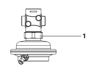
- Dismount impulse tubes.
- Loosen union nut 1.
- Remove actuator.
Mounting
- Place actuator at the valve and align, observe position of the impulse tube connections.
- Screw on union nut 1 and tighten, torque 100 Nm.
Replacement of Trim Valve AVP, AVP-F


Dismounting
- Unscrew actuator (see above).
- Unscrew trim 2.
DN 25: with pipe tongs, wrap gum strips around the trim DN 40: with wrench SW 55 - Pull out trim.
Mounting
Mounting is carried out in reverse order. Only tighten with low torque, sealing is made with O rings.
- Danfoss can accept no responsibility for possible errors in catalogues, brochures and other printed material. Danfoss reserves the right to alter its products without notice. This also applies to products already on order provided that such alterations can be made without subsequential changes being necessary eady agreed.
- All trademarks in this material are property of the respective companies. Danfoss and the Danfoss logotype are trademarks of Danfoss A/S. All rights reserved.
- 40 | © Danfoss | DHS-SRMT/SI | 2016.05
FAQS
Q: Who should perform maintenance on the PCVPQ?
A: Maintenance work should only be carried out by qualified, trained, and authorized personnel to ensure safety and proper functioning of the device.
Q: What should be done before starting any assembly work?
A: Before assembly, ensure that the system is depressurized, cooled down, emptied, and cleaned to prevent injury and damage to the device.
Documents / Resources
 |
Danfoss DN 100- DN 250 Pilot Controlled Flow Rate and Differential Pressure Controller [pdf] Instructions VI.JA.H3.5B, DN 100- DN 250 Pilot Controlled Flow Rate and Differential Pressure Controller, DN 100- DN 250, Pilot Controlled Flow Rate and Differential Pressure Controller, Controlled Flow Rate and Differential Pressure Controller, Flow Rate and Differential Pressure Controller, Differential Pressure Controller, Pressure Controller, Controller |