Danfoss COM 10C Oil Level Regulator

Technical Specification
| Model | COM 10C | COM 20C |
| Compatible Refrigerant | HFC, C02, HC | HFC, C02, HC |
| Compatible Oils | Mineral, Synthetic, Ester oils | Mineral, Synthetic, Ester oils |
| Max Operating pressure | 60 bar / 870 psi | 130 bar / 1885 psi |
| Test Pressure | 66 bar / 957 psi | 143 bar / 2074 psi |
| Burst Pressure | 180 bar / 2610 psi | 390 bar / 5656 psi |
| Maximum Opening Differential
Pressure |
40 bar / 580 psi | 80 bar / 1160 psi (100 bar at nominal voltage) |
| Supply Voltage | 24V AC 50Hz +10/-15%, 0.4A 230V AC 50Hz +10/-15% 0,04A |
24V AC 50Hz +10/-15%, 0.4A 230V AC 50Hz +10/-15% 0,04A |
| Media Temperature range | -40 to +80°C / -40 to +176°F | -40°C to +80°C / -40 to +176°F |
| Ambient/Storage Temperature range | -40 to +50°C / -40 to +122°F (static) | -40 to +50°C / -40 to +122°F (static) |
| Humidity | 0-80% RH (none condensing) | 0-80% RH (none condensing) |
| Alarm contact | Max 3A,230V AC dry contact | Max 3A,230V AC dry contact |
| Protection class | IP65 | IP65 |
| Sight glass | 11SMnPb37 Ni plated Pb< 0,035% | 11SMnPb37 Ni plated Pb< 0,035% |
| Oil connection | Brass CW 617N 7/16”-20 UNF male | Brass CW 617N 7/16”-20 UNF male |
| Filter | 100 micron mesh 80 | 100 micron mesh 80 |
| Vibration resistance (EN 60068-2-6) | max. 4g, 10… 250Hz | max. 4g, 10… 250Hz |
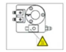
Installation
BOM diagram/part identification

- Screws (3 pcs.)
- Sight glass
- O-ring
- Body
- O-ring
- Adapter
- Flange ring
- O-ring
For installation of the product the refrigerant circuit area must be depressurized. Please note that the test pressure is not exceeded. Check parts for completeness. Sealing surfaces must be clean. Align the product horizontally (tol. +/- 1°). Remove transport lock before installation. The device is ready to install, do not disassemble prior to installation.
- Remove the sight glass from compressor.
- Place appropriate gasket or O-ring as per the adapter used.
- Use appropriate tightening torque as specified by compressor manufacture and the mounting adaptor used.


Electrical connection
Ensure country specific regulations. The operating voltage range must not be exceeded.
In case of line length > 6m the signal must be evaluated for interference and EMC. Further anti-interference measures may be required.
Signal lines must not run parallel to power lines. No moisture may penetrate the device. Wire the product as per the below diagram.

Service
The devices are maintenance-free when used under the conditions mentioned in this manual. In case of a defect, please replace the device.
Maintenance
Clean the filter in oil connection or replace the oil connection.
Disassembly
For the disassembly of the product the refrigerant circuit area must be depressurized. Switch off system Power. Remove product in reverse order of installation.
Disposal
Both the device as well as the transport packaging mainly consist of recyclable raw materials. Please dispose both according to the applicable legal regulations. Drain oil from the device and dispose safely.
General safety and warning
Safety and operational instructions
- Everybody in charge of the device’s installation, first operation, maintenance and repair, must have read and understood the installation manual as well as the safety relevant information.
- The installation of the products may only be carried out by educated and trained professional experts.
- The products may not be modified without permission. Every modification voids our liability for any damage caused by such modification.
- Only put the installation in operation once the product has been securely fitted and it is gas-proof.
- Please make sure that the test pressure is not exceeded.
- If the permissible operating temperatures are exceeded, the product may stop functioning or become defective.
- It is recommended that the product should remain permanently switched on (even if the compressor is shut down).
- Make sure that at all times oil is upstream of the regulator (no discharge gas)
- The coil becomes hot during operation.
- Before restart of compressors after a long period of standstill the oil level has to be checked on the sight glass of product.
- Do not remove plug from coil when device is powered on.
- Working on CO2 refrigeration Systems require a specific skill and training in handling CO2 as a refrigerant. The qualification and expert knowledge of the refrigerant personnel must conform to the respectively valid guidelines.
- Observe the high-pressure levels of CO2 refrigerants (critical temperature 31.06°C and 73,6 bar). At still stand the pressure in the system will rise and there is a risk of bursting. Installation of safety| pressure relief valves should be carried out acc. EN 378 and EN 13136. Take measures to prevent relief valve blockage due to dry ice during venting. Do not install pipe work to the outlet of the pressure relief valves.
- The product may be utilized exclusively for refrigeration and heat-pump applications. For this purpose, the limitations listed on the label as well as in the “Technical Data” must be observed. Any other use is considered improper. The product may only be utilized with the media listed on the manual. Application with other media is only allowed upon approval by Danfoss.
- Liability for injury or damage caused by the incorrect use of the device lies solely with the user.
Any information, including, but not limited to information on selection of product, its application or use, product design, weight, dimensions, capacity or any other technical data in product manuals, catalogues descriptions, advertisements, etc. and whether made available in writing, orally, electronically, online or via download, shall be considered informative, and is only binding if and to the extent, explicit reference is made in a quotation or order confirmation. Danfoss cannot accept any responsibility for possible errors in catalogues, brochures, videos and other material.
Danfoss reserves the right to alter its products without notice. This also applies to products ordered but not delivered provided that such alterations can be made without changes to form, fit or function of the product.
All trademarks in this material are property of Danfoss A/Sor Danfoss group companies. Danfoss and the Danfoss logo are trademarks of Danfoss A/S. All rights reserved.
Documents / Resources
 |
Danfoss COM 10C Oil Level Regulator [pdf] Installation Guide COM 10C, COM 20C, COM 10C Oil Level Regulator, Oil Level Regulator, Regulator |
 |
Danfoss COM 10C Oil Level Regulator [pdf] Installation Guide COM 10C, COM 20C, COM 10C Oil Level Regulator, COM 10C, Oil Level Regulator, Level Regulator, Regulator |
 |
Danfoss COM 10C Oil Level Regulator [pdf] Installation Guide COM 10C, COM 20C, COM 10C Oil Level Regulator, COM 10C, Oil Level Regulator, Level Regulator |


