Danfoss BHO 80 Series Control Box Base Unit

Specifications
- Product Name: OBC 80 series
- Model Variants: OBC 81, OBC 81A, OBC 82, OBC 82A, OBC 84, OBC 85B
- Functions: Boiler thermostat, High temperature cutout, Ignition unit transformer, External alarm, Phase wire, Neutral wire, Oil preheater, Hold relay, Remote reset
Application
The oil burner controls in the OBC 80 series are used to control and monitor one or two-stage oil burners with or without a preheater. The OBC 84.10 is used for burners with oil firing rates of 30 kg/h or above, and for hot air devices. Other OBC controls are used for oil burners with oil firing rates below 30 kg/h.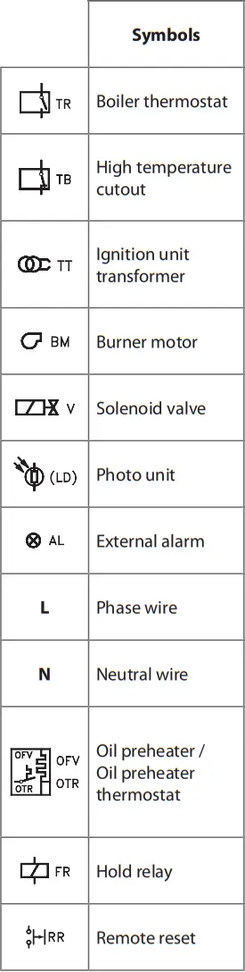
Mounting
Push the control’s contact plugs into the base with 12 connection terminals. A spring system holds the control and base together and can be released by pressing a screwdriver into the slot.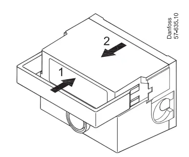 A front plate with knockouts or a front plate designed for PG 11 screwed connections can be used.
Electrical connections in the base for the various types.


- If using an LD or LDS photo unit, the blue wire must be connected to terminal 11 and the black wire to terminal 12. If using a UV sensor, the blue wire must be connected to terminal 11, the black wire to terminal 12, and the brown wire to terminal 1.
- If the preheater is not used, short-circuit terminals 3 and 8.
- If the control is equipped with a remote reset switch connected to terminal 9, this switch must only be activated manually.
- On some OBC 80 models, the ignition unit may be freely connected to either terminal 6 (TT1) or terminal 7 (TT2).
Note: On the OBC 85 the boiler thermostat (TR) must always be connected to terminal 7, and the high temperature cutout (TB) must always be connected to terminal 1.
Function
The OBC controls the cut-in and cut-out of the oil burner’s components and monitors that the combustion cycle is performed safely. When the boiler thermostat (TR) cuts in, heating of the oil in the oil preheater (OFV) will begin. Once the release temperature is reached and the oil preheater’s thermostat (OTR) cuts in, the burner motor will start the pre-purge, and power will simultaneously be applied to the ignition (TT1/TT2). Following the pre-ignition and pre-purge time, the oil will be released by opening valve V1 being opened. On two-stage burners, V2 will subsequently be opened. On OBC controls without post-purge, power will be cut off when the boiler thermostat opens after the heating period, and all relays at the outputs will open and be ready for the next start-up cycle. On the OBC 85 control the power is not cut off when the boiler thermostat opens, as power is still needed for the burner motor so that post-purge can occur. Instead, a timer function ensures that the burner motor continues to run until the end of the post-purge time. If the thermostat cuts in before the end of the postpurge time, the control will interrupt the postpurge and start a new cycle with pre-heating.
Operating information
OBC 80 controls are equipped with a two-colored LED that displays both the operating status and can indicate the causes of errors leading to lockout. In the event of an operating lockout, the cause of the error can be read out as a flash code by holding down the reset button for at least 5 seconds and then releasing it. Undervoltage will, however, be displayed automatically. Reset can be performed directly in alarm mode (constant red light) or flash code mode by pressing the reset button for at least 0.5 seconds but no more than 3 seconds. In flash code mode, it is possible to return to alarm mode by holding down the reset button again for at least 5 seconds.
Normal operation
When the boiler thermostat (TR) cuts in, the reset button flashes green. As soon as the preheater thermostat (OTR) cuts in, the reset button lights constantly green. When the boiler thermostat cuts out, the green light turns off. On the OBC 85, the light does not turn off until the post-purge period ends.
Errors during operation


- If the mains voltage falls below 185 V before start-up, the control will be blocked from starting. If the mains voltage falls below 170 V during operation, the oil supply and burner will be stopped. In both cases, the reset button will automatically flash 8 times. When the mains voltage reaches 185 V, the control will restart as normal. Please note that the control cannot be reset if the mains voltage is below 170 V.
- If the mains voltage exceeds 264 V, the control will automatically enter alarm mode. The purpose of the overvoltage cut-out is not simply to protect the electronics in the control, but also the other components in the burner.
- If light is registered in the final stage of the pre-purge time, the control will not release oil and will enter alarm mode.
- If no flame is established at the start, i.e., by the end of the safety time, the control will enter alarm mode.
- In the event of a flame failure during operation, the oil supply will be cut off after no more than 1 sesecondand the control will restart the burner. If flame failure occurs more than three times in the same operating period (TR connected), the control will enter alarm mode. Only one restart is allowed in the same operating period for OBC 84.10.
- If the release temperature in the preheater is not reached within 10 minutes, the control will enter alarm mode.
Flame signal check
- No flame/dark ≤ 5 MA
- Flame/light ≥ 65 MA


Troubleshooting
The OBC 80 series is approved by the latest EN 298:2012 norm, which sets more stringent requirements for the monitoring of safety functions than previous norms. It is therefore important to ensure proper connection by following the diagrams shown to avoid alarms. When replacing the control in connection with service, please ensure that:
- LD/LDS photo unit is connected to terminals 11 and 12. Common 0 on terminal 2 or connected auxiliary terminals must not be used. Replacing the photo unit is always recommended when replacing the control.
- If a certain function is not used, e.g., remote reset on terminal 9, the connection cannot be used as an auxiliary terminal. Instead, the extra auxiliary terminals in the base must be used.
- The ignition is connected to terminal 6, though this does not apply to controls with alternate outputs for ignition on terminal 7 (TT2).
- If an inverter that converts 12/24 V DC to 230 V AC is used, ensure that the inverter is capable of producing a sinusoidal AC voltage. If the voltage is not sinusoidal, the electronics will be overloaded (burn out). There is also a risk that the control will detect an undervoltage.
- The photo unit/UV sensor is positioned correctly in the burner so that the correct flame signal is generated. UV sensors are particularly sensitive, as they are very directional to prevent the ignition spark from being regarded as false light.
- The photo unit/UV sensor is not sooty.
- The insulation of the associated wiring is not degraded, as this can cause leakage currents that the control will register as errors at the inputs or outputs.
- The boiler thermostat switch contacts are not worn or coated, as this can cause periodic supply power cuts.
- The cables to and from the control are positioned so that they cannot generate electrical noise. Please be particularly aware that high-voltage cables from the electronic ignition must not be placed against or wound around the other electrical or electronic components, such as the control itself and the pump’s solenoid valve.
Note: Automatic controls in the OBC 80 series can only be reset while the supply voltage is connected.
Approvals
The controls in the OBC 80 series are approved by EN 298:2012:
Technical data
| Rated voltage | 230 V~ |
| Voltage range | 195 – 253 V~ |
| Frequency | 50 – 60 Hz |
| Supply fuse | max. 10 A |
| Enclosure | IP 40 |
| Ambient temperature | -20 – +60°C |
| Transportation & storage temperature | -30 – +70°C |
| Undervoltage protection | < 170 V |
| Protection class | II |
| Pollution degree | 2 |
Terminal loads
| Terminal | Max. operating current |
| 3 | 5 A |
| 4 | 1 A |
| 5 | 1 A |
| 6 / 7 | 1 A |
| 8 | 5 A |
| 10 | 1 A |
Note: Total operating current max. 5 A.
Conversion / Service
| BHO 60 series | BHO 70 series | OBC 80 series |
| – | BHO 71.10 | OBC 81.10 |
| – | BHO 71A.10 | OBC 81A.10 |
| BHO 64 | BHO 72.10 | OBC 82.10 |
| BHO 64.1 | BHO 72.11 | OBC 82.11 |
| BHO 64 A | BHO 73.10 | OBC 82A.12 |
| LOA 44 | BHO 74.10 | OBC 84.10 |
FAQs
Q: What are the main functions of the OBC 80 series?
A: The main functions include boiler thermostat control, high temperature cutout safety feature, ignition unit transformer operation, external alarm signaling, phase and neutral wire connections, oil preheater functionality, hold relay operation, and remote reset capability.
Q: How can I schedule operations using the time function?
A: To schedule operations using the time function, access the control panel, and set parameters for pre-purge, safety time, and post-purge as needed. The unit will execute these operations based on the programmed schedule.
Documents / Resources
 |
Danfoss BHO 80 Series Control Box Base Unit [pdf] Installation Guide OBC 81, OBC 81A, OBC 82, OBC 82A, OBC 84, OBC 85B, BHO 80 Series Control Box Base Unit, BHO 80 Series, Control Box Base Unit, Box Base Unit, Base Unit |


