
Danfoss AxisPro Servo Performance Proportional Directional Valve Owner’s Manual

AxisPro is a game changing machine control valve. Its embedded intelligence simplifies traditionally complex control practices. Plug and play design reduces machine build time, and its ability to predict potential maintenance issues increases machine reliability.

AxisPro level 1KBH valves, can be used to control machine motions in open loop or closed loop control applications. The valve receives its analog command input on the 7-pin, main, connector from an external axis control device.

AxisPro level 2 KBH valves, can be used to control machine motion in open or closed loop control applications. The valve can receive its analog command input on the 7-pin connec- tor from an external axis control device or, with the available on-board motion control feature activated (via Danfoss Pro-FX Configure), can close the external control loop around the actuator on the valve (taking feedback signal from cylinder or motor) – eliminating the separate motion controller. In this case the AxisPro valve receives a position, speed or force command and will create its own valve command needed to comply with the requested machine motion. In addition, digital communications over the CANopen bus is available for machine control or monitoring purposes.
Introduction
General Description
Built on the proven KBH servo Proportional Valve technology, the AxisPro Proportional Valve provides a range of control capabilities in a modular design. These solenoid operated proportional valves offer high dynamic performance which enables them to be used in closed-loop control applications.
Unique benefits from AxisPro
Reliable, extended uptime is enabled by valve and systems diagnostics capability. LED lens provides on-valve diagnostics information for level-1 valves. Access to systems and machine health data can be made available via CANopen networked valves and systems data collected from external sensors input to level-2 valves.
Leverage inventory of AxisPro valves by configuration through software. One valve SKU can serve multiple needs: Level-1 va lves can be configured via Danfoss’s Pro-FX™ Configure software tool for optional command signal: Voltage or current, as well as activating the “enable”-pin. Level-2 valves can also have CAN bus activated and control modes selected and configured: VSC for valve-spool control, or for axis- control drive modes: DPC Cylinder position control, DSC Speed control, DFP Force/Pressure control, DPQ Pressure/ Flow control. User applications can be developed in Danfoss’s Pro-FX Control software tool, which is based on the popular C ODESYS development environment. This feature is available o ption on level-2 valves allowing the use of pre-developed motion control blocks from Danfoss’s Pro-FX Control library or custom developed solutions that can be loaded into a “white space” reserved in the on-board controller memory.

Model Code

To find available product configurations go to www.danfoss.com

To find available product configurations go to www.danfoss.com
Spool Sleeve Details

Spool Data
Spool Symbols

Pressure and Minimum Flow Rates

Performance Curves


Operating Data
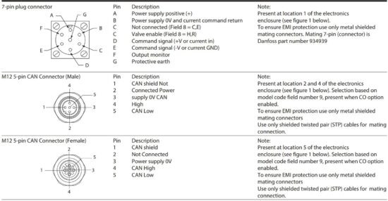
Connector Details


Software Information
KBH1
- Analog commanded spool control.
- Analog command source configuration options.
- Monitor output signal configuration options.
- Enable input signal enable/disable option.
KBH2/KBH3
- KBH 1capability.
- Sensor port configuration options. Configurable position, Speed, Pressure, Force and SSI Sensors.
- CANopen control modes (device
options vary per available hardware options).
– valve spool position control (VPOC/VSC).
– drive speed control (DSC).
– drive force/pressure control (DFPC/DFP).
– drive position control (DPC).
– drive pressure/flow control (Danfoss DPQ). - CANopen DSP306 compliant electronic data sheet (EDS).
- Diagnostic configuration options.
All levels and models are compatible with the Danfoss Pro-FX:
For the latest revision, please visit www.danfoss.com
EtherCAT Version:
-EtherCAT Slave Device
-PDO communication 100us ring time 2ms refresh rate
-100/10Mbit data rate
-SDO communication (COE)
-PDO dynamic mapping support (8 parameters)
-ESI file available
-TCP port:80 webserver, 300 (Profx tool) planned via EOE
-Profx tool access via CANopen
-training material available for TwinCAT connectivity Ethernet/IP Version:
-Ethernet/IP Adapter Device
-Assembly package for Process Data 2ms refresh rate
-100/10Mbit data rate
– two ports supported with daisy chaining, DLR support
– Class 3 explicit message support
-EDS file available
-TCP ports: 80 (webserver) 300 (Profx tool)
-Muticast support
Profinet Version:
-Protocol IO-Device
-Cyclic 5ms data exchange
-Conformance Class 2
-PROFINET IO specification: V 2.4
-100/10 Mbit RT compatible
-Acyclic data exchange via Read Write Data
-Records
-Two ports both can be used as access, build in Switch
-GDML file for Level1 and Level2
-TCP ports: 80 (webserver) 300 (Profx tool)
Download Pro-FX, Technical Information and Support Materials from Danfoss’s Website: www.danfoss.com
Install the Danfoss Pro-FX Configure PC application tool. Installation is supported on a wide range of Windows based operating systems including Windows 10/11 32 bit and 64 bit.
The Pro-FX configure installation provides several options for PC USB peripheral CANbus adapters supported by the software. During installation the user can choose to install drivers for an available CANbus adapter.
The adapters supported by Pro-FX Configure are:
• PCAN-USB* PEAK-System Technik GmbH (http://www.peak-system.com)
• ValueCAN Intrepid Control Systems, Inc. (http://www.intrepidcs.com)
• Leaf-Light Kvaser AB (http://www.kvaser.com)
* The PCAN-USB adapter is recommended for compatibility with Danfoss Pro-FX: Control development environment used with KBS4DGV-xxx and other DanfossPro-FX products it is also included in the TEQ-470-A-10 test box.
Electrical Information
Block Diagram Voltage
Input (Field 8 = 1)
Wiring connections must be made via the 7-pin plug mounted on the amplifier. See page 18 of this leaflet and Danfoss’s Installation Wiring
Practices for Vickers Electronic
Products, leaflet 2468.
Recommended cable sizes are:


Power cables:
For 24V supply
0.75 mm2 (18 AWG) up to 20m (65 ft)
1.00 mm2 (16 AWG) up to 40m (130 ft)
Signal cables:
0.50 mm2 (20 AWG)
Screen (shield):
A suitable cable would have 7 cores, a separate screen for the signal wires and an overall screen.
Cable outside diameter 8.0 – 10.5 mm (0.31 – 0.41inches)
See connection diagram on page 16.
Electrical Information
Block Diagram Current
Input (Field 8 = 2,3,4,5)
Wiring connections must be made via the 7-pin plug mou nted on the amplifier. See page 19 of this leaflet and Danfoss’s
Installation Wiring Practices for Vickers Electronic Products, leaflet 2468. Recommended cable sizes are:
Power cables:
For 24V supply
0.75 mm2 (18 AWG) up to 20m (65 ft)
1.00 mm2 (16 AWG) up to 40m (130 ft)
Signal cables:
0.50 mm2 (20 AWG)
Screen (shield):
A suitable cable would have 7 cores, a separate screen for the signal wires and an overall screen.
Cable outside diameter 8.0 – 10.5 mm (0.31 – 0.41 inches)
See connection diagram on page


Warning
All power must be switched off before connecting/disconnecting any plugs.
Wiring Connections Voltage
Output (Field 9 = 1)
■ Spool position monitor voltage (pin F) will be referenced to the KB valve local ground (pin B).

Wiring Connections for Voltage mode (Field 10 = R/H) Valves with Enable Feature
▲ Note: In applications where the valve must con-form to European RFI/EMC regulations, the outer screen (shield) must be connected to the outer shell of the 7 pin connector, and the valve body must be fastened to the earth ground. Proper earth grounding practices must be observed in this case, as any differences in command source and valve ground po-tentials will result in a screen (shield) ground loop.

Wiring Connections Current Output (Field 9 = 2)
■ Spool position monitor voltage (pin F) will be referenced to the KB valve local ground (pin B).

Wiring Connections for Current mode (Field 10 = R/H) Valves with Enable Feature
▲ Note: In applications where the valve must conform to European RFI/EMC regulations, the outer screen (shield) must be connected to the outer shell of the 7 pin connector, and the valve body must be fastened to the earth ground. Proper earth grounding practices must be observed in this case, as any differences in command source and valve ground potentials will result in a screen (shield) ground loop.

Warning
Electromagnetic Compatibility (EMC)
It is necessary to ensure that the valve is wired up as above. For effective protection of the user electrical cabinet, the valve subplate or manifold and the cable screens should be connected to efficient ground points. The metal 7 pin connector part no. 934939 should be used for the integral amplifier.
In all cases both valve and cable should be kept as far away as possible from any sources of electromagnetic radiation such as cables carrying heavy current, relays and certain kinds of portable radio transmitters, etc.
Difficult environments could mean that extra screening may be necessary to avoid the interference.
It is important to connect the 0V lines as shown above. The multi-core cable should have at least two screens to separate the demand signal and monitor output from the power lines.
The enable line to pin C should be outside the screen which contains the demand signal cables.
To ensure EMI protection use only metal shielded mating connectors.
Warning
All power must be switched off before connecting/ disconnecting any plugs.
Installation Dimensions
mm (inch)
KBH1-05 with Pressure Reducer

KBH1-05 without Pressure Reducer

KBH2-05 with Reducer and Pilot Sensors

Mounting Surfaces
Mounting Surface Interface to ISO 4401 (Size 05)
This interface conforms to: ISO 4401-05-05-0-05
ANSI/B93.7M (and NFPA) size 05
CETOP R35H4.2-05
DIN 24340 Form A10

Application Data
Fluid Cleanliness
Proper fluid condition is essential for long and satisfactory life of hydraulic components and systems. Hydraulic fluid must have the correct balance of cleanliness, materials and addi-tives for protection against wear of components, elevated viscosity and inclusion of air.
The following recommendations are based on ISO cleanliness levels at 2 μm, 5 μm and 15 μm. For products in this catalog the recommended levels are:
17/15/12
Danfoss products, as any components, will operate with apparent satisfaction in fluids with higher cleanliness codes th an those described. Other manufacturers will often recomme nd levels above those specified.
Experience has shown, however, that life of any hydraulic components is shortened in fluids with higher cleanliness codes than those listed above. These codes have been prov-en to provide a long trouble-free service life for the products shown, regardless of the manufacturer.
Hydraulic Fluids
Materials and seals used in these valves are compatible with antiwear hydraulic oils, and aryl phosphate esters. The extreme operating viscosity range is 500 to 13 cSt (2270 to 70 SUS) but the recommended running range is 54 to 13 cSt (245 to 70 SUS).
Installation
The proportional valves in this catalog can be mounted in any attitude, but it may be necessary in certain demanding applications, to ensure that the solenoids are kept full of hydraulic fluid.
Good installation practice dictates that the tank port and any drain port are piped so as to keep the valves full of fluid once the system start-up has been completed.
Service Information
The products from this range are preset at the factory for optimum performance; disassembling critical items would de- stroy these settings. It is therefore recommended that should any mechanical or electronic repair be necessary they should be returned to the nearest Danfoss repair center.
The products will be refurbished as necessary and retested to specification before return. Field repair is restricted to the replacement of the seals.
Products we offer:
- Cartridge valves
- DCV directional control valves
- Electric converters
- Electric machines
- Electric motors
- Fluid Conveyance
- Gear motors
- Gear pumps
- Hydraulic integrated circuits (HICs)
- Hydrostatic motors
- Hydrostatic pumps
- Industrial hydraulics
- Orbital motors
- PLUS+1® controllers
- PLUS+1® displays
- PLUS+1® joysticks and pedals
- PLUS+1® operator interfaces
- PLUS+1® sensors
- PLUS+1® software
- PLUS+1® software services, support and training
- Position controls and sensors
- PVG proportional valves
- Steering components and systems
- Telematics
Hydro-Gear
www.hydro-gear.com
Daikin-Sauer-Danfoss www.daikin-sauer-danfoss.com
Danfoss Power Solutions is a global manufacturer and supplier of high-quality hydraulic and electric components. We specialize in providing state-of-the-art technology and solutions that excel in the harsh operating conditions of the mobile off-highway and industrial markets as well as the marine sector. Building on our extensive applications expertise, we work closely with you to ensure exceptional performance for a broad range of applications. We help you and other customers around the world speed up system development, reduce costs and bring vehicles and vessels to market faster.
Danfoss Power Solutions – your strongest partner in hydraulics and mobile
Go to www.danfoss.com for further product information.
We offer you expert worldwide support for ensuring the best possible solutions for outstanding performance. And with an extensive network of Global Service Partners, we also provide you with comprehensive global service for all of our components.
Danfoss
Power Solutions (US) Company 2800 East 13th Street
Ames, IA 50010, USA
Phone: +1 515 239 6000
Danfoss
Power Solutions GmbH & Co. OHG Krokamp 35
D-24539 Neumünster, Germany Phone: +49 4321 871 0
Danfoss
Power Solutions ApS Nordborgvej 81
DK-6430 Nordborg, Denmark Phone: +45 7488 2222
Danfoss
Power Solutions Trading
(Shanghai) Co., Ltd.
Building #22, No. 1000 Jin Hai Rd Jin Qiao, Pudong New District Shanghai, China 201206 Phone: +86 21 2080 6201
Danfoss can accept no responsibility for possible errors in catalogues, brochures and other printed material. Danfoss reserves the right to alter its products without notice. This also applies to products
already on order provided that such alterations can be made without subsequent changes being necessary in specifications already agreed.
All trademarks in this material are property of the respective companies. Danfoss and the Danfoss logotype are trademarks of Danfoss A/S. All rights reserved.
Danfoss | March 2024
Read More About This Manual & Download PDF:
Documents / Resources
 |
Danfoss AxisPro Servo Performance Proportional Directional Valve [pdf] Owner's Manual KBH-05, 11 Series, AxisPro Servo Performance Proportional Directional Valve, AxisPro, Servo Performance Proportional Directional Valve, Performance Proportional Directional Valve, Proportional Directional Valve, Directional Valve, Valve |


