Contents
hide
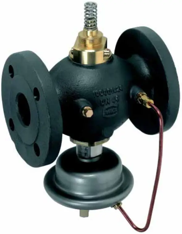
Danfoss AIQM, AIQM5 Flow Rate Controller With Motorised Valve
Product Information
Specifications
- Type: AIQM, AIQM5
- Model: AIQM DN 40
- Application: Flow rate controller with motorised valve
- Languages: English, Dansk, Deutsch, Polski, Francais
Product Usage Instructions
Safety Notes
- To avoid injury or damage, carefully read and follow the instructions. Only qualified personnel should handle assembly, startup, and maintenance. Depressurise the system before any work.
Definition of Application
- The AIQM controller is used with an electrical actuator for water and water-glycol mixtures in heating, district heating, and cooling systems. Follow technical data on rating plates for proper use.
Assembly
- Permissible installation positions: IP 54 protection for actuator recommended. IP 52 protection for the actuator is also suitable.
Installation
- Follow the system manufacturer or operator’s instructions. Ensure proper assembly and disassembly with a depressurised system.
Pressure Test
- Perform pressure test according to guidelines to ensure system integrity and safety.
Filling the System
- Properly fill the system with the required fluid while following recommended procedures.
Setting of Flowrate Restriction
- Adjust flow rate restriction as needed for optimal system performance.
Troubleshooting
- Refer to the troubleshooting section for guidance on detecting and resolving issues.
Safety Notes
 To avoid injury to persons and damage to the device, it is necessary to carefully read and observe these instructions.
- Necessary assembly, start-up, and maintenance work may be performed only by qualified and authorised personnel.
- Prior to assembly and disassembly, depressurised system!
- Please comply with the instructions of the system manufacturer or system operator.
Definition of Application
- In combination with an electrical actuator (AME, AMV 11.,31.), the controller AIQM is used of water, water glycol mixtures for heating, district heating and cooling systems.
- The technical data on the rating plates determine the use.
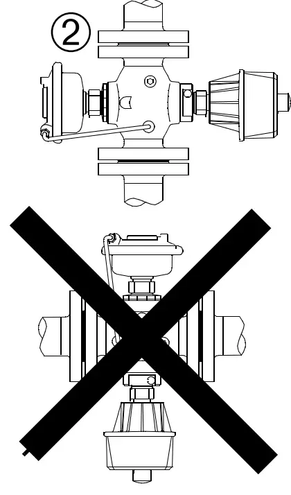
Assembly
Permissible Installation Positions
- Recommended type of protection actuator: IP 54
- Recommended type of protection actuator: IP 52
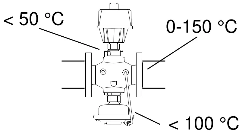
- Permissible Temperatures
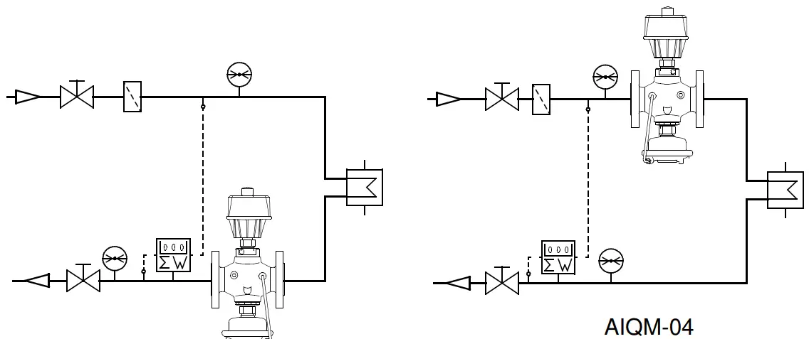
- Installation Position and Scheme
- Supply or return flow
- Permissible Temperatures
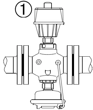
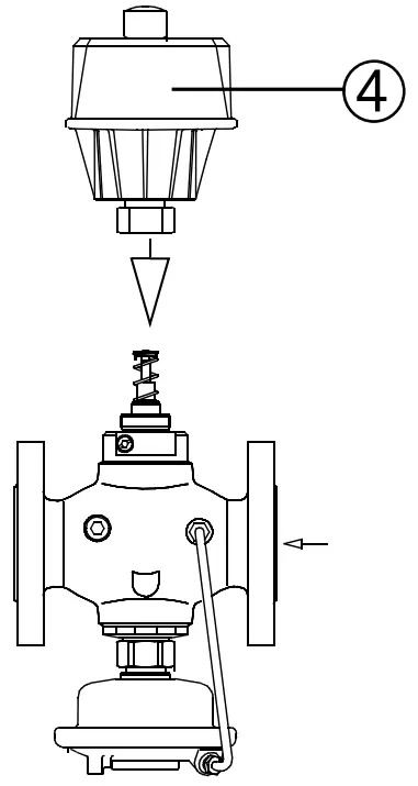
Installation
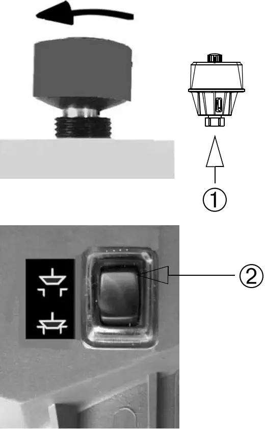
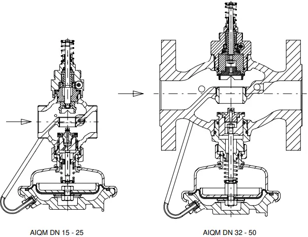
- Install the strainer ➀ before the controller.
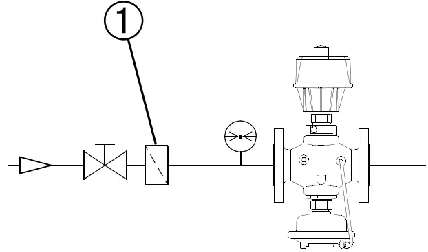
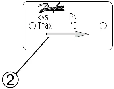
- Observe the flow direction ➁ on the rating plate.
- Design with welded end ➂ pin only ➃ weld
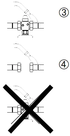
- Design with welded end ➂ pin only ➃ weld
- Rinse system.
- If necessary, carry out pressure tests; see section “Pressure Tests“.
- Then, mount the electrical actuator ➄.
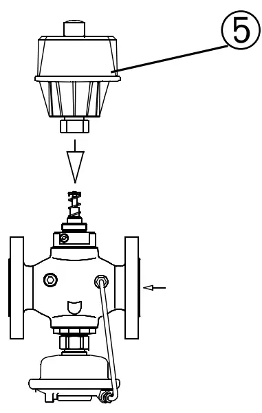
- Keep to the Assembly
- Instructions for the respective actuator, „Assembly“ section.
Insulation
Pressure actuator ➀ can be insulated up to a medium temperature of 100°c.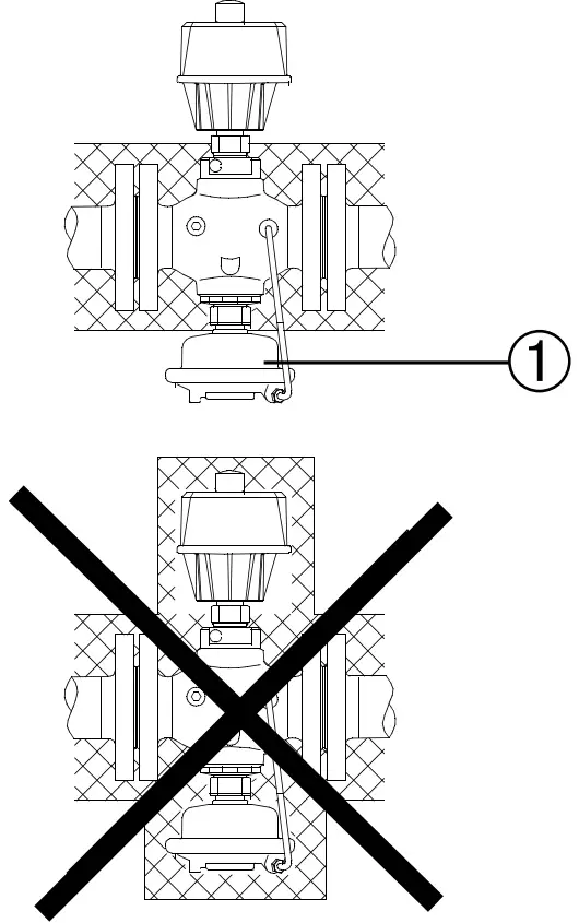
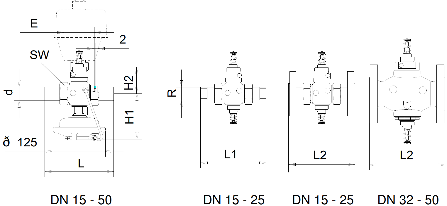
Dimensions
- Conic male thread acc. to DIN 2999
- Flanges PN 25: Connection dimensions acc. to DIN 2501, seal form C
| DN | 15 | 20 | 25 | 32 | 40 | 50 | |
| R 1) | R1/2 | R3/4 | R 1 | ||||
| SW | mm | 32 | 41 | 50 | 63 | 70 | 82 |
| d | 21 | 26 | 33 | 42 | 48 | 60 | |
| E | 65 | 70 | 75 | 100 | 110 | 130 | |
| L | 139 | 154 | 159 | 184 | 204 | 234 | |
| L1 | 125 | 146 | 169 | ||||
| L2 2) | 130 | 150 | 160 | 180 | 200 | 230 | |
| H1 | 119 | 125 | 125 | 155 | 159 | 159 | |
| H2 | 58 | 65 | 65 | 81 | |||
Pressure Tests
- Do not test closed valves ➀ with pressures of more than 16 bar.
- Otherwise, the valve may be damaged.
- Observe the following.
Prior to Pressure Tests:
- Open valve.
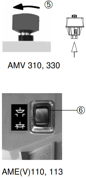
- retract stem ➁ :
- AMV310, 330 see ➄
- AME(V)110, 113 see ➅
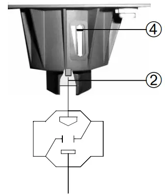
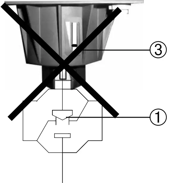
Observe the stroke indicator:
- ➂ Valve CLOSED
- ➃ Valve OPEN
- Note: For actuator AME(V)113 with a safety return function, the stem is extended if the power supply is switched off.
Handling:
- Slowly increase pressure.
Filling the System
- Take care that the valve is OPEN; see above „pressure test“.
Setting of Flow Rate Restriction
- Adjustment AIQM5 see Instructions actuator AMV(E)210, 213.
Adjustment AIQM see following:
- The adjustment of the flow is carried out by limiting the valve stroke ➀.
There are two possibilities:
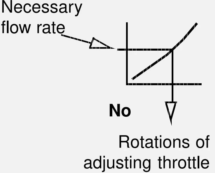
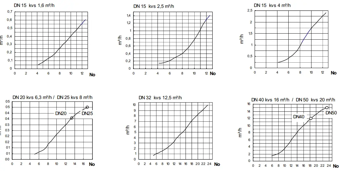
- Adjustment with adjusting curves.
- Adjustment with heat meter.
Adjustment with adjusting curves
- The system need not be active to be adjusted!
- Settings are carried out in 2 steps.
Step 1: Setting the Valve Stroke
- Close valve ➁ by turning the adjusting screw ➂ to its stop.
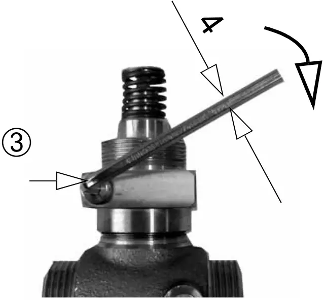
- Select curve
- Turn adjusting screw ➀ by this number of rotations counter-clockwise.
- The setting of the valve stroke ➁ is completed.
- The adjusting screw ➂ may be sealed.
Step 2: Setting the Actuator Stroke
- If not yet done, install the actuator ➃; see the Assembly Instructions for the respective actuator in the “Assembly” section.
- Set the stroke of the actuator. See Assembly Instructions for the respective actuator, “Stroke Setting“ section.
Adjusting Curves
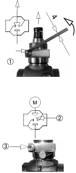
Adjustment with Heat Meter
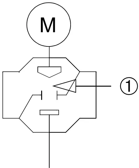
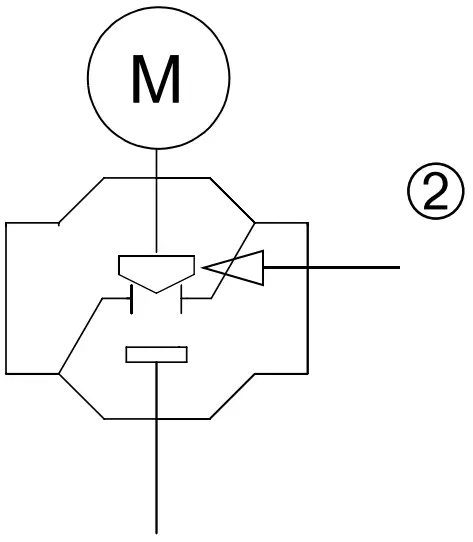
- Retract the actuator stem to its stop:
- AMV310, 330 see ➀.
- AME(V)110, 113 see ➁.
- Observe the position of the stroke indicator ➂:
- Position ➃: Stem ➄ is retracted.
- The position depends on the stroke set.
- Take care that system or bypass ➅ is completely opened.
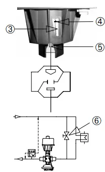
- Observe the heat meter.
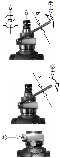
Turning counterwise ➆ increases the flow.
Turning clockwise ➇ reduces the flow. - When the heat meter shows the required value, shortly throttle the system and then re-open it (e.g. using the electrical actuator).
- Verify the flow rate.
- The valve setting is completed.
- The adjusting screw ➈ may be sealed.
- To set the Actuator Stroke, see step 2.
Troubleshooting
| Fault | Possible cause | Remedy |
| The flow rate was not reached. | The pressure difference across the valve is too low. | Verify pressure difference; minimum pressure difference required see next section. |
| The flow rate restriction. | Verify setting; see section „Setting of Flow Rate Restriction“. | |
| The valve is dirty. | Uninstalling the valve, cleaning it, or replace it is necessary. | |
| The flow rate is limited by the electrical actuator. | Check the electrical actuator. | |
| The flow rate is too high. | A control line is dirty. | Dismount control line, check control line and connections for free passage, and clean if necessary. |
| The pressure actuator is defective, e.g., the diaphragm is leaky. | Dismount and check the actuator, and replace it if the diaphragm is leaky. | |
| The flow rate restriction. | Verify setting; see section „Setting of Flow Rate Restriction“. |
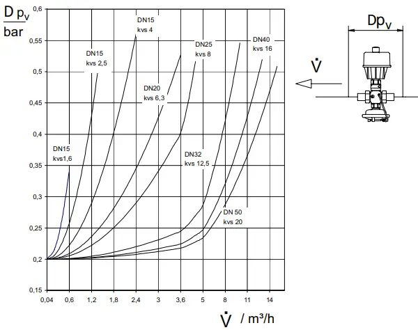
Minimum Pressure Difference
- Minimum pressure difference required from the control valve
FAQ
- Q: Who should perform assembly and maintenance work?
- A: Only qualified and authorised personnel should handle assembly, startup, and maintenance tasks.
- Q: What languages are the instructions available in?
- A: The instructions are available in English, Danish, Deutsch, Polski, and Francais.
- Q: What is the recommended protection level for the actuator during installation?
- A: IP 54 protection for the actuator is recommended, but IP 52 protection is also suitable.
Documents / Resources
 |
Danfoss AIQM,AIQM5 Flow Rate Controller With Motorized Valve [pdf] Instructions AIQM, AIQM5, AIQM AIQM5 Flow Rate Controller With Motorized Valve, AIQM AIQM5, Flow Rate Controller With Motorized Valve, Controller With Motorized Valve, Motorized Valve |