Danfoss AFP 2 Differential Pressure Controller
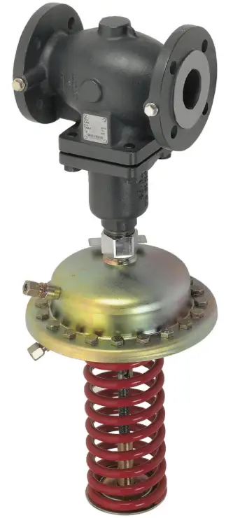
Specifications
- Model: AFP 2 / VFG 2 (21) DN 15-250, VFG 22 (221) DN 65-250
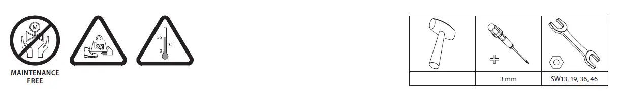
- Maintenance: Maintenance Free
- Size Range: DN 15-50
- Operating Pressure: PN 16, PN 25, PN 40
Safety Notes
Prior to assembly and commissioning, to avoid injury of persons and damages of the devices, it is absolutely necessary to carefully read and observe these instructions.
Necessary assembly, start-up, and maintenance work must be performed only by qualified, trained and authorized personnel.
Prior to assembly and maintenance work on the controller, the system must be:
- depressurized,
- cooled down,
- emptied and
- cleaned.
Please comply with the instructions of the system manufacturer or system operator.
Definition of Application
The controller is used for pressure reduction of water and water glycol mixtures for heating, district heating and cooling systems.
The technical data on the label plates determine the use.
Scope of Delivery 1
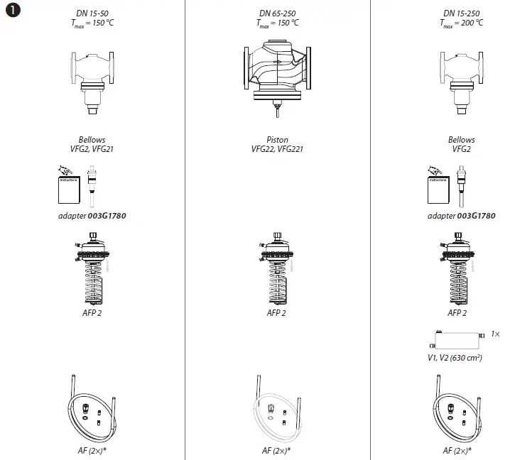
Impulse tube AF, accessory 2

Assembly
Admissible Installation Positions
- media temperatures up to 150 °C: Can be installed in any position.
- media temperatures > 150 °C. Installation permitted only in horizontal pipelines with the actuator oriented downwards.
Installation Location and Installation Scheme 3 4

The valve is open without pressure and is closing on rising pressure.
System must be protected behind the pressure reducer by a safety monitoring unit ①.
Valve Installation 5

- Install strainer ① before the controller.
- Rinse system prior to installing the valve.
- Observe flow direction ② on valve body. Flanges ③ in the pipeline must be in parallel position and sealing surfaces must be clean and without any damage.
- Install valve.
- Tighten screws crosswise in 3 steps up to the max. torque.
Actuator Installation 6 7 8

The actuator stem must be screwed into the valve stem. Spring on the pressure actuator is factory adjusted (released) for proper installation.
- Remove the spindle protection cup and release the valve spindle by removing the nut, washer and cardboard tube.
- Align the actuator stem with the valve stem, connect both stems and turn gently the whole pressure actuator clockwise with both hands, until the stems are fully connected (valve stem fully screwed into the actuator stem).
- Release the uninon nut by pulling out the blocking spring.
- Tight the union nut
- Release the pressure actuator by turning it counter clockwise for approximately half a turn.
- Observe the position of impulse tubes connection to the valve and align the actuator accordingly.
- Hold the actuator in the position and tight the union nut to the valve with 100- 120 Nm torque.
Impulse Tube mounting 9 10

Which impulse tubes to use?
The impulse tube set AF (2×) ❻① can be used: Order No.: 003G1391 or use the following pipes:
| Stainless steel | Ø 10×0.8 | DIN 17458,
DIN 2391 |
| Steel | Ø 10×1 | DIN 2391 |
| Copper | Ø 10×1 | DIN 1754 |
The impulse tube ③ can be connected directly to the valve ④ o tr o the pipeline ⑤.
ventilation socket, do not connect impulse tube.
Connection to the valve 11

- Remove plug ① at the valve.
- Screw in threaded joint G 1/4 ② with copper seal, Torque 40 Nm.
– or –
Connection to the Pipeline ❽①
No connection downwards/upwards ②, could bring dirt/air into an impulse tube.
- Cut pipe in rectangular sections ③ and deburr.
- For copper pipe: insert sockets ④ on both sides.
- Verify the correct position of the cutting ring ⑤.
- Press impulse tube ⑥ into the threaded joint up to its stop.
- Tighten union nut ⑦ Torque 40 Nm.
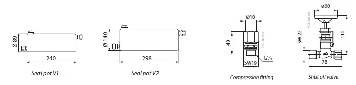
When installing seal pots ❽⑧, please observe the Installation Instructions for the seal pots.
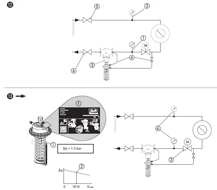
Insulation 12
For media temperatures up to 120 °C the pressure actua tor may be insulated ①.
Dismounting 13

Danger
Danger of injury by hot water
Prior to dismounting the depressurize system or use shut off valves on the impulse tubes! ①
Carry out dismounting in following steps: ②
- Fasten pressure actuator with the safety bands to the fixed points in surroundings
- Before releasing the actuator, fully release the union nut
- Hold the pressure actuator with both hands, and release it by turning it counter clockwise ~30 turns. During turning, control the actuator weight all the time to prevent unexpected fall of detached actuator.
- Carefully remove the actuator from the valve.
Before installing actuator back to the valve, setting spring must be fully released again.
Leak and Pressure Test
Observe max. permitted pressure, see below.
- The pressure behind the valve ② must not exceed the pressure before the valve ①.
- Observe nominal pressure ⑤ of the valve.
- Prior to pressure tests, it is absolutely necessary to remove the impulse tube at the valve ④.
- Close connections with plugs G ¼ ISO 228.
Max. pressure [bar] with connected impulse tube:
Max. test pressure [bar] with disconnected impulse tube must not exceed the plant testing pressure and must always be lower than 1.5 × PN.
Non-compliance may cause damage at the controller ③.
Filling the System, Start-up
The pressure ② behind the valve must not exceed the pressure ① before the valve.
Non-compliance may cause damage at the controller ③.
- Open shut-off devices ④ that are possibly available at the impulse tubes.
- Slowly open valves in the system.
- Slowly open shut-off devices ⑤ in the supply flow.
- Slowly open shut-off devices ⑥ in the return flow.
Putting out of Operation
- Slowly close shut-off devices ⑤ in the supply flow.
- Slowly close shut-off devices ⑥ in the return flow.
Setpoint Adjustment
Set-point range see rating plate ①
- Start-up of system, see section
- Set flow rate at the fitting ② after the pressure reducer ③,to about 50 % of max. flow rate ④
- Adjustment of the pressure behind the valve ⑤
- Observe pressure indicators.
- Turning to the right ⑥ increases the set-point (stressing the spring)
- Turning to the left ⑦ reduces the set-point (un-stressing the spring)
- The set-point adjuster ⑧ may be sealed.
- Release the not yet used pointer ⑨, move it to the set position and fix it with the screw
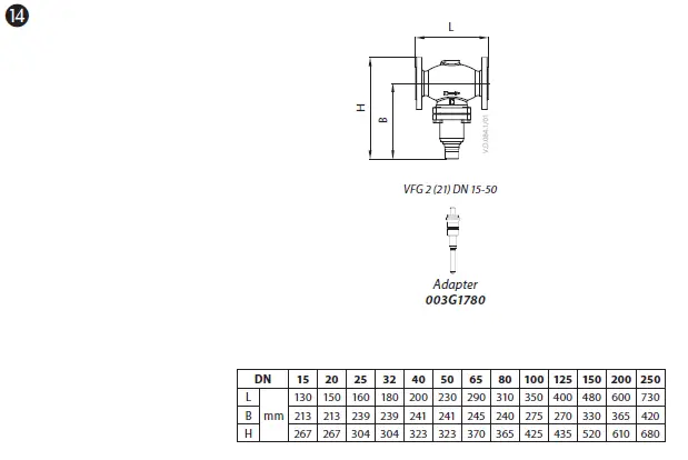
Dimensions ⓮
Flanges: connection dimensi ons acc. to DIN 2501, seal form C

Danfoss A/S Climate
Solutions • danfoss.com • +45 7488 2222
Any information, including, but not limited to information on selection of product, its application or use, product design, weight, dimensions, capacity or any other technical data in product manuals, catalogues descriptions, advertisements, etc. and whether made available in writing, orally, electronically, online or via download, shall be considered informative, and is only binding if and to the extent, explicit reference is made in a quotation or order confirmation. Danfoss cannot accept any responsibility for possible errors in catalogues, brochures, videos and other material Janfoss reserves the right to alter its products without notice. This also applies to products ordered but not delivered provided that such alterations can be made without changes to form, fit or function of the product. All trademarks in this material are property of Danfoss A/S or Danfoss group companies. Danfoss and the Danfoss logo are trademarks of Danfoss A/S. All rights reserved.
FAQ
- Q: Is maintenance required for this product?
A: The product is maintenance-free for normal operation. No specific maintenance is needed. - Q: What is the recommended pressure range for this product?
A: The recommended pressure range is between 1-3 bar for optimal performance
Documents / Resources
 |
Danfoss AFP 2 Differential Pressure Controller [pdf] User Guide 21, 22, 221, AFP 2 Differential Pressure Controller, AFP 2, Differential Pressure Controller, Pressure Controller |


