D and D Technologies CSI724 Round Latch

Specifications
- Gate Compatibility: Round Post and Gate Frame
- Gap Variance: 1 – 2 1/4 inches (25mm – 57mm)
- Tools Required: Electric or cordless drill (low clutch settings), Phillips No.1 screwdriver, 5/16 hex-head drill drive, 11/64 inch drill bit for pre-drilling metal
Product Usage Instructions
Step #1 – Main Latch Body Installation
- Determine the desired height of the latch on the gate.
- Prop the gate open and slide the Release Knob to the up position at the rear of the Latch Body.
- Insert the Round Post Bracket into the back of the latch body at a slight angle until it snaps firmly in place.
- Secure the Round Post Bracket by inserting screws as indicated.
Step #2 – External Access Kit Installation
- Ensure the latch is in the unlocked position and prop the gate open.
- Slide the Release Knob to the up position at the rear of the Latch Body.
- Attach the Push Rod to the Large Return and secure it in place.
- Lock the Release Knob in place and rotate the Push Rod to the horizontal position.
- Lock the Push Button Assembly against the Round Post Bracket and secure it in place.
Additional Installation Steps
- Position the Striker Body on the gate frame and mark fixing slots.
- Drill pilot holes inside the marked slots using a 11/64 inch drill bit.
- Secure the Striker Body onto the gate frame using appropriate screws.
Installation
STEP #1 — MAIN LATCH BODY
INSTALLATION PROCEDURE
This latch is designed to be fitted to the “opening” side of the gate. See notes at right re right- or left-hand installation, and also for the fitting of the Round Post Bracket (A) to the Latch Body
- Post sizes: 17/8–2″, 23/8″, 27/8″ (48–51mm, 60mm, 73mm).
- Gate frame sizes: 13/8″ and 15/8″ (35mm and 41mm).
- Gap Variance: 1″ -21/4″ (25mm – 57mm)
- Tools: Electric or cordless drill (use low clutch settings), Phillips No.1 screwdriver, 5/16″ hex-head (Tek) drill drive (for use in electric/cordless drill), 11/64″ [4.5mm] drillbit for pre-drilling metal.
INSTALLING THE ROUND POST BRACKET

- Once the “handing” is determined, insert the Round Post Bracket into the back of the latch body at a slight angle, as shown: rotate the Post Bracket in the direction of the arrows until it snaps firmly in alignment on the latch body. Insert a single short screw (Screw 1) in the center hole inside the bracket, and a short screw top and bottom (screws 2 & 3) of the latch.
INSTALLATION NOTES & PROCEDURE
- This latch is designed, ideally, to be fitted to the inside (i.e. house or tennis court side) of the gate. If installing to the outside (i.e. street side) of the gate ensure there is hand access to operate the latch…or, if this pack contains an “EXTERNAL ACCESS KIT”, ensure it is fixed to this latch before installing the entire latch onto the gate (see over for details).
- For 23/8″ (51mm) fence posts and 15/8″ (41mm) gate frames, no adapters are required.
- This latch kit includes special adapter shims for fitting the latch to posts and gate frames of varying diameters (see S1, S2 & S3). The adapters have the diameter they are designed for molded into them. If required, place two identical adapters (S1 or S2) into their corresponding positions on the inside the Round Post Bracket facing the Fence Post.

- Determine the desired height of the latch on the gate. Hold the latch in place on the post and close the gate.
- Position the Striker Body “C” on the gate frame by engaging the striker bolt into the latching tongue. (Check whether the adaptor shim ‘S3’ needs to be applied to fit your gate frame.) When all latch components are aligned correctly, use the pencil to mark inside the four fixing slots of the Striker Body “C”.
- Place all latch components aside and drill a pilot hole in the center of the marked slots using a 11/64″ (4.5mm) drill-bit. Remember that centering the screws inside the slots allows future adjustment for gate sag.
- Secure the Striker Body “C” firmly onto the gate frame using four of the large hex-head Tek screws supplied.
- Open the gate. Place the Latch Assembly back onto the latch post and then close the gate. Engage the Striker Bolt through the latch tongue again, aligning the main Latch Body on the latch post so that the Striker Bolt will close in the center of the latch tongue (the Rivet marks the center of the latching zone).
- 6. Hold the Latch Assembly in place and mark the post through the two main screw-
fixing holes at the side of the Round Post Bracket. - Remove the Latch Assembly and drill the pilot holes where marked.
- Secure the Latch Assembly using the two remaining hex-head Tek screws supplied.
- Check latch operation to ensure smooth, reliable latching. Your LOKKLATCH is now ready for use.
If this pack does not have an “External Access Kit”, you can purchase one from your supplier.
STEP #2 — EXTERNAL ACCESS KIT
The External Access Kit (EAK) allows a gate to be opened and locked from the opposite side to the latch. The EAK is connected to the Latch Body by a Push Rod.
INSTALLATION PROCEDURE
- With the latch in the unlocked position, prop the gate open. Slide the Release Knob to the up position at the rear of the Latch Body. Take the Push Rod and, holding it vertically, slide the Large Return through the slot in the side of the Latch Body as shown in diagram 1. Be sure the Large Return protrudes completely through to the other side of the Latch Body.

- Lower the Release Knob to the down position so that it encloses the Large Return of the Push Rod. Turn the key to lock the Release Knob in place. Rotate the Push Rod to the horizontal position as shown in diagram 2.

- To aid with installation, the Push Button is locked. Place the Push Button Assembly against the opposite side of the Round Post Bracket from the Latch Body.
- Place the Small Return of the Push Rod into the hole on the side of the Push Button as shown in diagrams 3 & 4.

- Place the Small Return of the Push Rod into the hole on the side of the Push Button as shown in diagrams 3 & 4.
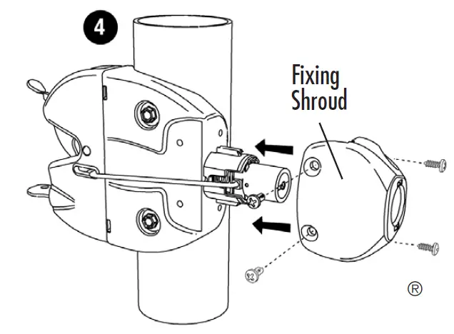
- With the Small Return of the Push Rod firmly inside the hole on the Push Button, slide the Fixing Shroud over the Push Button until the Fixing Shroud sits firmly into the corresponding Round Post Bracket molding (see diagram 5). This will leave the Push Rod at a slight angle, which is normal.

- Secure the Fixing Shroud to the Round Post Bracket with the four small screws using the Phillips No. 1 screwdriver. Unlock the Push Button and check for smooth operation. The External Access Kit is now ready for use.
(Note: Locking the External Access Assembly only locks the Push Button. It does not lock the Latch Body, which is lockable separately.)
More Info
For a downloadable Adobe Acrobat (.PDF) version of our Limited LIFETIME WARRANTY, go to our website at www.ddtechglobal.com
FAQ
- Q: What tools are required for installation?
- A: You will need an electric or cordless drill with low clutch settings, a Phillips No.1 screwdriver, a 5/16 hex-head drill drive, and an 11/64 inch drill bit for pre-drilling metal.
- Q: How do I determine the correct height for installing the latch?
- A: Determine the desired height of the latch on the gate based on your specific needs and gate design.
- Q: Can I install the External Access Kit separately?
- A: The External Access Kit should be fixed to the latch before installing the entire unit for proper functionality.
Documents / Resources
 |
D and D Technologies CSI724 Round Latch [pdf] Owner's Manual CSI724, CSI724 Round Latch, CSI724, Round Latch, Latch |