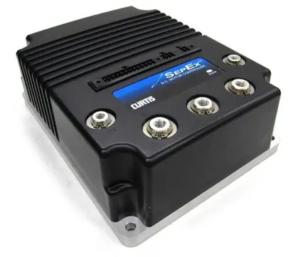
Curtis 1268-ITS Controller Sourcefy
Specifications:
- Product Name: Curtis 1268-ITS
- Part Numbers: 1268-5401, 5404, 5411, 5412, 5415, 5416, 5418, 5502, 5505, 5508, 5509
- Voltage Compatibility: + – 36V/48V Battery Pack
Product Usage Instructions
Steps to Perform Before Control Installation:
- CHECK MOTOR WINDINGS:
- Set VOM to RESISTANCE ().
- Measure A1 to A2 (0.2 – 2), F1 to F2 (0.8 – 3), A1 to F1 (OPEN), F1 to motor case (>5M).
- CHECK MAIN SOLENOID:
- Disconnect all wires from the main solenoid.
- Measure solenoid coil (100 – 250).
- Connect VOM leads to main solenoid lugs and attach jumpers for testing.
- CHECK THE CART WIRE HARNESS:
- Inspect wire harness connectors for issues and repair or replace pins as needed.
Note: Ensure all the above checks are within specified ranges before installing the controller to avoid warranty void.
Solenoid Replacement Recommendation:
It is advised to replace the solenoid when replacing the controller. Popular replacement White Rodgers solenoids are now available for convenience.
- The Curtis 1268-5411 controller, a key component for 36-48V industrial machines, offers precise speed and torque control. Designed for heavy-duty vehicles, this 48V controller enhances performance and efficiency. Installation is user-friendly: securely connect the controller to your machine’s power system, ensuring all safety protocols.
- During repairs, remember to disconnect the power supply to avoid hazards. The Curtis 1268 controller stands out for its durability and reliability, minimizing downtime. For replacements, choose compatible parts and follow the manufacturer’s guidelines. This controller not only optimizes machine operation but also contributes to the longevity and safety of your industrial equipment.
Product Specifications
|
Part Type |
Speed Controller |
|
Fitment |
Direct Replacement |
|
Output Current |
400A |
|
Voltage |
36/48V |
|
Field 2 Minute Current Rating |
50 |
|
Logic Input Voltage (High) |
20V |
|
Logic Input Voltage (Low) |
7.5V |
|
Logic Input Current |
10mA |
|
PWM Operating Frequency |
16 kHz |
|
Electrical Isolation to Heatsink (min) |
500 VAC |
|
KSI Input Voltage (min) |
16.8V |
|
KSI Input Current (typical) |
160 mA w/o Programmer 200 mA with Programmer |
|
Throttle Type |
5kΩ 3-Wire Potentiometers 0–5V Throttles |
|
Large Terminals |
3 (B-, M, B+) |
|
Small Terminals |
2 (F1, F2) |
|
Connectors |
3 (24-pin, 6-pin, 4-pin) |
|
Environmental Rating |
IP64, IP67 |
|
Color |
Black |
|
Dimensions |
L229xW178xH81 mm |
|
Cross References |
CL7008642, CT1268-5411, EZ611173, HU4044650R, PHAX00002106, YP550046324R, YP5500463-24R, 7008642, 611173, 4044650R, AX00002106, 550046324R, 5500463-24R |
|
Suggested Accessories |
76-1415-GOLF , 76-908HRNS48V , 76-908R3648BNJO , 94-CM174 , 100-586117111 , 100-586120111 , 43-8012-30 , 76-1268-TURF , 76-1313K-3231 , 76-1415-GOLF , 76-908HRNS48V , 76-908R3648BNJO , 94-CM174 , 100-586117111 , 100-586120111 , 43-8012-30 , 76-1268-TURF |
Features
The Curtis 1268-5411 controller is meticulously designed to offer unparalleled control over your vehicle’s speed and torque, ensuring a reliable and consistent performance across a range of industrial applications.
- Versatile Voltage Support: Compatible with both 36V and 48V systems, accommodating a wide range of industrial vehicles.
- Precise Speed Adjustment: Allows for exact control settings to match specific task requirements.
- Durable Construction: Built to withstand the rigors of heavy industrial use without compromising functionality.
- Integrated Diagnostics: Simplifies troubleshooting with built-in diagnostic capabilities.
- High Current Output: Delivers up to 400A, supporting robust operations in demanding environments.
Benefits:
Optimizing your vehicle’s efficiency and operational safety, the Curtis 1268-5411 controller not only improves performance but also contributes to the longevity and reliability of your machinery.
- Improved Efficiency: Enhances energy management, leading to lower operational costs and extended battery life.
- Increased Safety: Advanced features reduce risks of malfunctions, ensuring safer operation environments.
- Reduced Maintenance Costs: High-quality materials and smart design decrease the need for frequent repairs.
- User-Friendly Installation: Streamlined setup process allows for quick and easy installation without specialized tools.
- Environmental Resistance: Offers protection against dust, moisture, and temperature variations, ensuring reliable performance in diverse conditions.
Signs of a Faulty Controller
- Intermittent Operation: The vehicle experiences unexpected stops or starts.
- Reduced Efficiency: Noticeable decrease in the vehicle’s performance, especially in speed control.
- Physical Damage: Signs of wear, such as corrosion or other visible damage to the controller casing.
- Error Codes: Controller reports faults or error codes during operation.
- Overheating: The unit becomes excessively hot during use, indicating potential internal issues.
Recommended Use/Applications
The Curtis 1268-5411 36-48V 400A ITS SX Control, designated as Model 1268, is utilized in various high-performance golf carts that require enhanced speed and torque control. It’s particularly suited for golf carts used in rugged or demanding environments, such as those found in large resorts, golf courses, or industrial complexes.
Frequently Bought Together
Are you looking to maximize the performance of your Curtis 1268-5411 controller? Here are additional products that complement its operation:
- 1268-5505 36-48V 500A Masterdrive Cntrl
- 1268-5504 36-48V 500A (0-5K) Sx Control
- 1268-5418 Masterdrv 36-48V 400A Its
- 1268-5411 36-48V 400A (Its) Sx Control
- 1268-5402 G – 36-48V 400A (0-5K)sx Ctl
Part Numbers: 1268-5401, 5404, 5411, 5412, 5415, 5416, 5418, 5502, 5505, 5508, 5509
This sheet is provided to aid in the installation of your remanufactured CURTIS controller. Upon installation, you may encounter problems that may, or may not, be due to a faulty controller. The following steps must be taken to help diagnose a possible cart fault or faulty controller. An analog or digital volt ohm meter (VOM) will be needed to perform these checks.
WARRANTY WILL BE VOID
If These Steps are Not Performed Before Installing The Control
STEPS TO PERFORM BEFORE CONTROL INSTALLATION
- CHECK MOTOR WINDINGS:
- Set your VOM to RESISTANCE (Ω).
- To test the resistance of VOM leads, please touch the meter leads together.
- Subtract this measurement from each test below to get your true measurement.
- With motor disconnected, measure A1 to A2. This should measure approximately BETWEEN .2Ω and 2Ω.
- With motor disconnected, measure F1 to F2. This should measure approximately BETWEEN .8Ω and 3Ω.
- With motor disconnected, measure A1 to F1. This should measure OPEN.
- With motor disconnected, measure F1 to motor case. This should measure greater than 5MΩ.
- CHECK MAIN SOLENOID:
- Disconnect all wires from the main solenoid.
- Set your VOM to RESISTANCE (Ω).
- Measure the solenoid coil. This should measure 100Ω – 250Ω (depending on solenoid type).
- Connect VOM leads to the main solenoid lugs.
- Attach jumpers from main battery positive and negative to the coil (small terminals).
- Meter should jump from infinity to LESS THAN .3Ω.
- Remove jumpers and reconnect solenoid wiring from the harness. (If suppression diode is present,
the non-banded side must go to the wire from J1 pin 17 from the controller. Be sure to check diode functionality with VOM prior to install. If pre-charge resister is installed, please remove. This control is equipped with an internal resistor, and installing one on the solenoid could cause damage to the control.)
- CHECK THE CART WIRE HARNESS:
- Check the connectors on the wire harness for corrosion, loose, broken, burnt or missing pins.
- Repair or replace pins as necessary.
36V/48V Battery Pack
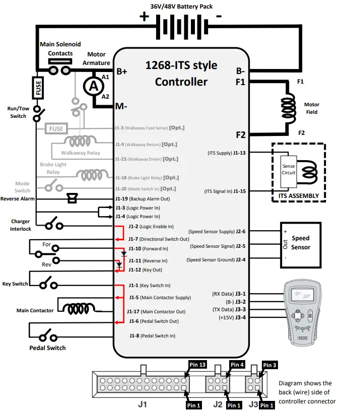
Generic Golf (1268-ITS) Troubleshooting Sequence
FOR SAFETY, ALWAYS LIFT THE DRIVE WHEELS OFF THE GROUND WHEN TROUBLESHOOTING!
THE FOLLOWING TESTS ARE CONDUCTED WITH RUN-TOW/MAINTENANCE SWITCH IN THE RUN POSITION AND WITH A GOOD BATTERY PACK VOLTAGE MEASUREMENT. ALSO, THE CONNECTOR MUST BE ATTACHED TO THE CONTROLLER WHEN MAKING THESE CHECKS. YOU WILL NEED TO ‘BACK PROBE’ THE PINS FROM THE WIRE SIDE OF THE CONNECTOR. USE A PAPERCLIP IF NECESSARY.
Attach Voltmeter Negative (-) lead to main Battery Negative (-) for the following tests.
Use the following sequence when checking individual pins (don’t skip steps). If you find a fault, do not move on to the next step until the fault is corrected:
- Measure the voltage at the main battery positive post (let’s call it Pack Voltage)
- Pin J1-3 Must be Pack Voltage
If not Pack Voltage, check wiring, Run/Tow switch and fuse for an open condition - Pin J1-4 Must be Pack Voltage
If not Pack Voltage, check wiring, Run/Tow switch and fuse for an open condition - Pin J1-2 With charger disconnected, must be Pack Voltage
If not Pack Voltage, check wiring and charger interlock switch for an open condition - Pin J1-7 With charger disconnected, must be Pack Voltage
If not Pack Voltage, check continuity between J1-2 and J1-7. If open, internal trace in controller has been damaged - Pin J1-10 With F/R Switch in Reverse, must equal 0 volts
If not 0 volts, check wiring and F/R Switch for a shorted condition. If wiring tests good, check continuity between J1-10 to J1-11, if shorted, internal controller damage. - Pin J1-10 With F/R Switch in Forward, must equal Pack Voltage
If not Pack Voltage, check wiring and F/R Switch for an open condition - Pin J1-11 With F/R Switch in Forward, must equal 0 volts
If not 0 volts, check wiring and F/R Switch for a shorted condition - Pin J1-11 With F/R Switch in Reverse must equal Pack Voltage
If not Pack Voltage, check wiring and F/R Switch for an open condition - Pin J1-12 With F/R Switch in Forward or Reverse must equal Pack Voltage
If not Pack Voltage, and previous directional switch tests are good, then internal trace in controller has been damaged - Pin J1-1 With Key Switch On must equal Pack Voltage
If not Pack Voltage, check wiring and Key Switch for an open condition - Pin J1-5 With Key Switch On must equal Pack Voltage
If not Pack Voltage, check continuity between J1-1 and J1-5. If open, internal trace in controller has been damaged - Pin J1-17 With Key Switch On must equal Pack Voltage (Solenoid should NOT be engaged at this time)
If not Pack Voltage, check wiring and Key Switch for an open condition. Also check main contactor coil and wiring for an open condition. - Pin J1-6 With Key Switch On must equal Pack Voltage
If not Pack Voltage, check continuity between J1-6 and J1-1. If open, internal trace in controller has been damaged - Pin J1-8 With Pedal Up, must equal 0 volts
If not 0 volts, check wiring and Pedal Switch for a shorted condition - Pin J1-8 With Pedal Down, must equal Pack Voltage
If not Pack Voltage, check wiring and Pedal Switch for an open condition - Pin J1-17 With Key Switch On, and Pedal Down, must equal less than 1v (Solenoid should be engaged)
If not Pack Voltage, check solenoid coil/wiring for faulty condition. Ensure no active fault occurring - Pin J1-19 With F/R Switch in Neutral, must equal approximately Pack Voltage
If not approximately Pack Voltage, check wiring and Reverse Alarm for an open condition - Pin J1-19 With F/R Switch in Reverse, must equal less than approximately 1 volt (and backup alarm beeps)
If correct voltage, but no sound from reverse alarm, replace beeper - Pin J1-13 With Key Switch on, must equal 14 to 15 volts
If not 14 to 15 volts, remove ITS sensor and recheck. If voltage returns, check ITS sensor and wiring, ITS sensor or wiring may be faulty. If voltage does not return, controller may be defective - Pin J1-15 With Key Switch on, and Pedal up, must equal approximately .8 (+/- .3) volts
If voltage is out of tolerance, ITS may be defective. Replace as necessary. - Pin J1-15 With Key Switch on, and Pedal fully depressed, must equal approximately 2.0 (+/- .3) volts
If voltage is out of tolerance, ITS may be defective. Replace as necessary. - Pin J2-4 Must equal 0 volts
If not 0 volts, harness and/or harness connector is defective, check wiring - Pin J2-6 Must equal 14 to 15 volts
If not 14 to 15 volts, check wiring and check with Speed Sensor removed – if voltage returns to 14 to 15 volts, Speed Sensor may be faulty - Pin J2-5 While slowly turning the drive wheel, must toggle between 0 volts and approximately 5 volts
If not toggling, check wiring and if necessary replace Speed Sensor and/or magnet *** Note: This controller is capable of many optional features and functions that may or may not be present on your cart. *** See checks below for optional vehicle features - Pin J1-3 (If no wire in this position then skip this step, otherwise) must equal Pack Voltage
If not Pack Voltage, check wiring and Walkaway Fuse for an open condition - Pin J1-9 (If no wire in this position then skip this step, otherwise) must equal Pack Voltage
If not Pack Voltage, controller may be defective - Pin J1-23 (If no wire in this position then skip this step, otherwise) must equal Pack Voltage
If not Pack Voltage, check wiring and Walkaway Relay for an open condition - Pin J1-23 (If no wire in this position then skip this step, otherwise) while pushing on cart, must equal approximately 0 volts
If not approximately 0 volts, controller may be misprogrammed or faulty - Pin J1-18 (If no wire in this position then skip this step, otherwise), must equal Pack Voltage
If not approximately Pack Voltage, check wiring and Brake Light Relay coil for an open condition - Pin J1-20 (If no wire in this position then skip this step, otherwise) with Mode Switch open, must equal 0 volts
If not 0 volts, check wiring and Mode Switch for a shorted condition - Pin J1-20 (If no wire in this position then skip this step, otherwise) with Mode Switch closed, must equal Pack Voltage
If not Pack Voltage, check wiring and Mode Switch for an open condition - Pin J1-16 (If no wire in this position then skip this step, otherwise), must equal 0 volts
- Pin J1-22 (If no wire in this position then skip this step, otherwise), must toggle between approximately 0 and 2 volts and must be in sequence with the Status LED on top of the controller.
If not toggling between approximately 0 and 2 volts, check wiring and remote LED for an open condition
TROUBLESHOOTING CHART
LED DIAGNOSTICS
A built-in Status LED is visible through a window in the label on top of the controller. When the controller detects a fault, the Status LED flashes the 2-digit fault code. The code is flashed continuously until the fault is corrected. For example, code “3,2” – welded main contactor – appears as:

Helpful Hints
DO NOT UNDER ESTIMATE THE IMPORTANCE OF MOTOR RESISTANCE CHECKS AND MAIN SOLENOID CHECKS. MANY CART ISSUES ARE CAUSED BY BURNT/DAMAGED BRUSHES THAT WILL BE FOUND AS PART OF THE ARMATURE RESISTANCE CHECK. ALSO A SHORTED ARMATURE AND FIELD WITHIN THE MOTOR WILL DAMAGE THIS CONTROLLER.
Flight Systems Industrial Products also offers the following Technical Support options
Troubleshooting Manuals / Codes
www.shop.fsip.biz/en/content/technicaldocuments

Live Tech Support Chat
www.fsip.biz

Technical Support Forum
fsip.websitetoolbox.com
Phone Support
1-800-333-1194 (Option 4)
PRE-INSTALLATION INSTRUCTIONS MUST BE FOLLOWED OR WARRANTY WILL BE VOID
IMPORTANT! 1268- (ITS THROTTLE) TROUBLESHOOTING INFORMATION INCLUDED IN THIS PACKET
FAQ
Q: What should I do if I encounter problems after installing the Curtis controller?
A: If you face issues post-installation, follow the steps provided in the manual to diagnose possible faults in the cart or controller. Always ensure proper checks before installation to prevent warranty void.
What does the Curtis 1268-5411 controller do?
It controls speed and torque in 36-48V industrial vehicles, enhancing performance and efficiency.
How is the 48V controller installed in machinery?
Installation involves connecting it to the machine's power system, following safety protocols and manufacturer guidelines.
Can this controller work with machine models?
Yes, it's designed for versatile use across various 36-48V machines, but always check compatibility.
What are the key benefits of using the Curtis 1268 controller?
It offers improved efficiency, safety, and durability, reducing maintenance and operational costs.
How do I troubleshoot issues with this controller?
The controller includes diagnostic features for easy identification and resolution of problems.
Is the controller environmentally friendly?
Yes, its efficient operation supports sustainable industrial practices.
What should I consider when replacing this controller?
Choose compatible parts and follow the installation process as per the manufacturer's instructions.
Documents / Resources
 |
Curtis 1268-ITS Controller Sourcefy [pdf] Instructions 1268-5401, 5404, 5411, 5412, 5415, 5416, 5418, 5502, 5505, 5508, 5509, 1268-ITS Controller Sourcefy, 1268-ITS, Controller Sourcefy, Sourcefy |