Contents
hide
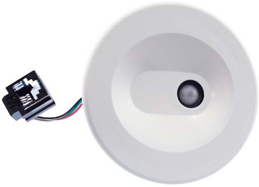
COOPERLIGHTING WLX-PS-SENSOR Tilemount Sensor Kit Without Control Module
FAQs
- Q: What is the range of the wireless radio?
- The wireless radio has a range of 75ft (25m) Line of Sight (LOS).
- Q: What type of control does the Tilemount Sensor Kit offer?
- The Tilemount Sensor Kit offers motion sensing, daylight dimming, and continuous 0-10V dimming control.
PRODUCT INFORMATION
- WaveLinx PRO Tilemount Sensor Kit without control module (WTE)
- Provides motion sensing, daylight dimming, and additional RTLS sensing capabilities outside of fixture-integrated components
- Typical Applications
- Office
- Education
- Healthcare
- Hospitality
- Retail Industrial
- Manufacturing
Product Certification*
- Meets latest ASHRAE Standard 90.1 requirements
- Meets the latest IECC requirements
- Meets latest CEC Title 24 requirements

Product Features
Compatibility

Overview
- The WaveLinx PRO Tilemount Sensor Kit is an integral part of the WaveLinx connected lighting (WCL) system and offers 120-277VAC 3 amp zero crossing relay control and continuous 0-10V dimming control of LED and non-LED loads.
- The intended use of the Tilemount Sensor Kit is to provide daylight dimming and control for connected downlight luminaires or other luminaires that do not support the WaveLinx PRO integrated sensor.
- The Tilemount Sensor Kit is powered by the 120-277VAC circuit it is controlling and allows simple electrical junction box mounting via ½” knock out or direct connection to the junction box attached to the connected luminaire.
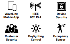
- The WaveLinx PRO Tilemount Sensor Kit operates on a wireless mesh network based on IEEE 802.15.4 standards and is controlled by the WaveLinx Area Controller.
Product Features & Benefits
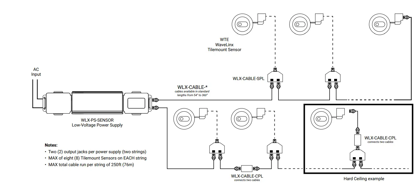
- External plenum-rated power source for multiple sensor connectivity (up to 16 sensors)
- Multiple pre-terminated plenum-rated cable options are available
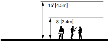
- Mounting heights of 8 to 15ft (2.4 to 4.5m)
- Provides passive infrared (PIR) motion coverage up to 500 sqft (46m2)
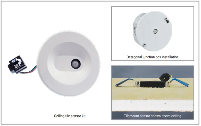
- Sensor installs into 1/2 – 3/4” (12 – 19mm) ceilings or octagonal junction boxes
- Hardware capable of Real-Time Location Services (RTLS) – WaveLinx CORE Locate license required
Order Information
- The WaveLinx PRO Tilemount Sensor kit and Power Supply are accessories to the WaveLinx connected lighting (WCL) system and require a WaveLinx Area Controller (WAC) for full functionality.
- The wireless tile mount sensor kit is used to provide occupancy sensing in spaces and can be mapped to other sensors in an area for maximum coverage and control.
- The wireless tile mount sensor kit is typically used to provide additional Real Time Location (RTLS) sensing points in space (WaveLinx CORE Locate license required) in addition to PIR motion sensing.
- Catalog Number
- Catalog Number
- Catalog Number
| Catalog Number | Description |
| WTE | Wavelinx PRO Tilemount Sensor Kit without Control Module |
| WLX-PS-SENSOR | Wavelinx PRO Tilemount Sensor Power Supply |
| WLX-CABLE-054 | Wavelinx PRO Sensor Cable 54in |
| WLX-CABLE-084 | Wavelinx PRO Sensor Cable 84in |
| WLX-CABLE-180 | Wavelinx PRO Sensor Cable 180in |
| WLX-CABLE-360 | Wavelinx PRO Sensor Cable 360in |
| WLX-CABLE-SPL | Wavelinx PRO Sensor Cable Splitter |
| WLX-CABLE-CPL | Wavelinx PRO Sensor Cable Coupler |
Required Accessories
All WaveLinx connected lighting (WCL) system accessories require at least one WaveLinx Area Controller (WAC) for communications. Ensure the bill of material includes one of the following components.
Catalog Number
| Catalog Number | Description |
| WAC2-POE | WaveLinx Area Controller G2, PoE-powered |
| WAC2-120 | WaveLinx Area Controller G2 with 120VAC to PoE Injector |
Optional Accessories
For connection to 120VAC outlets.
Catalog Number
| Catalog Number | Description |
| WPOE2-120 | 120VAC to PoE Injector |
Product Specifications
Key Features
- Kit Contents:
- Sensor
- 54” Plenum-rated cable
- Tile and 4” octagon mounting trim
- Easily enable 0-10V luminaires to be controlled by WaveLinx
- Provides closed-loop daylighting control of non-integrated luminaires
- Control module mounting to junction box or luminaire driver compartment
- Sensor installs into 1/2 – 3/4” (12 – 19mm) ceilings or octagonal junction boxes
- Ceiling white trims that can be painted for a custom appearance
- Mounting heights of 8 to 15ft (2.4 to 4.5m)
- Provides passive infrared (PIR) motion coverage up to 500 sqft (46m2)
- Hardware capable of Real-Time Location Services (RTLS)
- CORE Locate license required
- Energy calculations available through WaveLinx CORE
- Mechanical
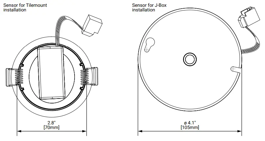
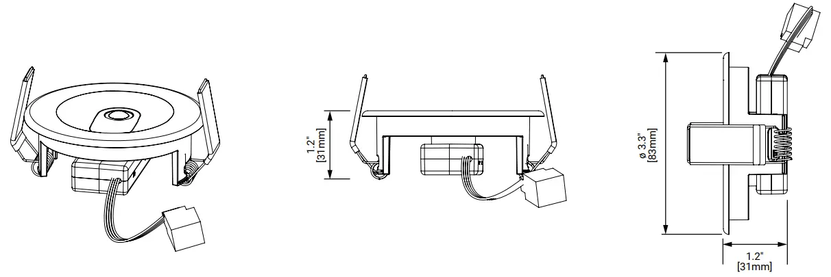
- Tilemount Sensor Size: 2.8” x 2.8” x 1.2” (70mm x 70mm x 31mm)
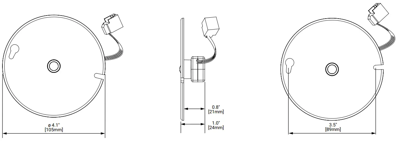
- J-Box Sensor Size: 4.1” x 4.1” x 1.0” (105mm x 105mm x 24mm)
- Environment:
- Operating temperature: -4°F to 131°F (-20°C to 55°C)
- Storage temperature: -40°F to 158°F (-40°C to 70°C)
- Relative humidity operating: 5% to 95% non-condensing
- For indoor use only
- Mounting Height: 8-15ft (2.4 to 4.5m)
- Ceiling hole diameter: 2.9” (73mm)
- Ceiling thickness: 0.5 to 0.75” (12 – 19mm) drop ceiling thickness
- Color: Matte white (field paintable trim)
- Housing: UV-stabilized plastic
- Electrical
- 120/277VAC incoming and switched power
- 10mA 0-10V sink (refer to driver specifications to calculate quantity supported)
- 3A LED loads
- Software Specifications
- Any number of sensors can be mapped to any number of zones
- Remote configuration of occupancy sensing and closed-loop daylighting
- Wireless Specifications
- Radio: 2.4GHz
- Standard: IEEE 802.15.4
- Transmitter Power: + 7dBm
- Range: 75ft (25m) LOS
- # of Walls: 2 interior walls standard construction
- Standards/Ratings*
- cULus Listed
- Meets latest ASHRAE Standard 90.1 requirements
- Meets the latest IECC requirements
- Meets latest CEC Title 24 requirements
- Environmental Regulations:
- RoHS Directive 2011/65/EU
- Warranty
- Five-year warranty standard
Dimensional Details
Mounting Height
Wiring Diagrams
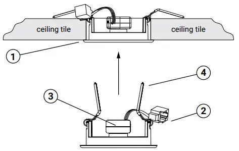
Tilemount Installation
- Step 1: Cut 2-7/8” (73mm) to 3” (76mm) diameter hole in the ceiling tile.
- Step 2: Connect plenum cable connectors.
- Step 3: Snap sensor body into ceiling trim.
- Step 4: Squeeze trim springs and insert them through the hole.
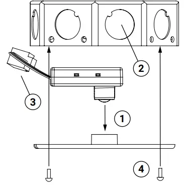
J-Box Installation
- Step 1: Snap the sensor body into the cover plate.
- Step 2: Pull the plenum sensor cable through the junction box knockout.
- Step 3: Connect plenum cable connectors.
- Step 4: Secure the sensor kit to the junction box.
Additional Dimensional Details – Tilemount Sensor
Additional Dimensional Details – J-Box Sensor
Field of View
TOP VIEW:
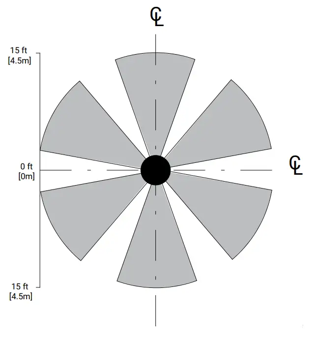
Notes:
- The coverage pattern shown above depicts the area below the luminaire where the integrated sensor system can detect occupancy.
- Spacing between fixtures should not exceed the coverage pattern of the sensor.
- Mounting height should not exceed the coverage shown.
- Exceeding these spacing/height guidelines will result in reduced integrated sensor performance.
SIDE VIEW:

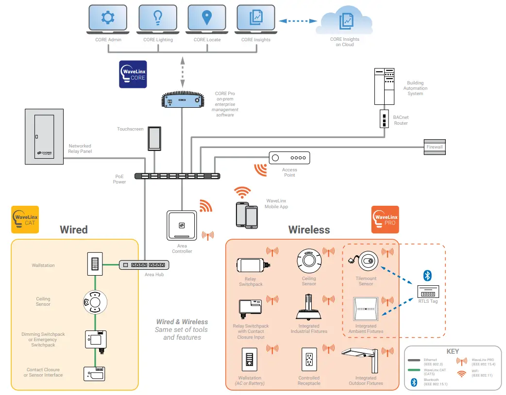
System Diagram
- This diagram shows the main components of the WaveLinx connected lighting system with CAT and PRO devices.
- The PRO devices communicate using wireless mesh technology based on the IEEE 802.15.4 standard. A PoE LAN connection for each WaveLinx Area Controller (WAC) is required for power and data access to the building lighting network.
- The CAT devices communicate over the category 5-based communication bus and control the light fixtures using a relay (on/off) and 0-10V output (dim/raise).
- WaveLinx Area Controllers (WAC) communicate with WaveLinx CORE Apps over the Ethernet network.
- View WaveLinx Network and IT Guidance Technical Guide
- Project
- Catalog #
- Type
- Prepared by
- Notes
- Date
CONTACT INFORMATION
- Cooper Lighting Solutions
- 1121 Highway 74 South
- Peachtree City, GA 30269
- P: 770-486-4800
- www.cooperlighting.com
- © 2024 Cooper Lighting Solutions
- All Rights Reserved.
- Specifications and dimensions are subject to change without notice.
Documents / Resources
 |
COOPERLIGHTING WLX-PS-SENSOR Tilemount Sensor Kit Without Control Module [pdf] Instruction Manual WTE, WLX-PS-SENSOR, WLX-CABLE-054, WLX-CABLE-084, WLX-CABLE-180, WLX-CABLE-360, WLX-CABLE-SPL, WLX-CABLE-CPL, WLX-PS-SENSOR Tilemount Sensor Kit Without Control Module, WLX-PS-SENSOR, Tilemount Sensor Kit Without Control Module, Kit Without Control Module, Without Control Module, Control Module, Module |