CONNECT TECH Rogue-X NVIDIA Computer on Module
Product Information
Specifications
- Model Number: CTIM-00082
- Revision: 0.04
- Date: 2022-12-01
- Manufacturer: Connect Tech
Product Features and Specifications
The product offers the following features and specifications:
- LED Locations
- Connector and Switch Locations – Module Side
- Push Button Switches
- Typical Installation
- Software
- Force Recovery Mode
- Power Consumption
- Cables
- Mechanical Drawings & Models
- Thermal Options
- Passive Heatsink (XHG305)
- Active Heatsink (XHG306)
- Assembly drawings
Product Overview
The product is a versatile module designed for various applications. It offers a range of features and specifications to meet different requirements.
Detailed Feature Description
- The product includes LED indicators for easy status monitoring.
- It also has connectors and switches located on the module side for convenient access. The push-button switches allow for easy control and operation. The module can be installed in a typical manner, and software is available for enhanced functionality. The force recovery mode helps in troubleshooting and resolving any issues.
- The product has low power consumption, ensuring efficient operation. Cables are provided for easy connectivity. Mechanical drawings and models are available for reference. Thermal options include both passive and active heatsinks for effective heat dissipation. Assembly drawings provide detailed instructions for installation.
Product Usage Instructions
LED Locations
The LED indicators are located on the module and provide visual feedback on the status of the product.
Connector and Switch Locations – Module Side
The connectors and switches are conveniently located on the module side for easy access and connectivity.
Push Button Switches
The push button switches on the product allow for easy control and operation. Refer to the user manual for specific functions and usage instructions.
Typical Installation
The product can be installed in a typical manner following the provided installation instructions. Ensure proper alignment and secure attachment.
Software
The product is compatible with software that enhances its functionality. Install the required software as per the provided instructions.
Force Recovery Mode
In case of any issues, the force recovery mode can be activatedto troubleshoot and resolve problems. Follow the instructions in the user manual to enter the force recovery mode.
Power Consumption
The product has low power consumption, ensuring efficient operation and minimal power usage.
Cables
Cables are provided with the product for easy connectivity. Use the appropriate cables as per your specific requirements.
Mechanical Drawings & Models
Refer to the mechanical drawings and models provided for detailed information on the physical dimensions and structure of the product.
Thermal Options
The product offers thermal options for effective heat dissipation. Choose between passive heatsink (XHG305) or active heatsink (XHG306) based on your specific needs.
Assembly Drawings
The assembly drawings provide step-by-step instructions for the proper installation and assembly of the product. Follow the provided instructions carefully for successful assembly.
FAQ
- Q: How do I activate the force recovery mode?
A: To activate the force recovery mode, follow the instructions provided in the user manual. Typically, it involves a combination of button presses or specific software commands. - Q: Can I use my own cables with the product?
A: Yes, you can use your own cables as long as they are compatible with the connectors on the product. Ensure proper cable specifications and connections for optimal performance. - Q: What is the power consumption of the product?
A: The product has low power consumption. Refer to the specifications section for detailed power consumption information.
PREFACE
Disclaimer
The information contained within this user’s guide, including but not limited to any product specification, is subject to change without notice.
Connect Tech assumes no liability for any damages incurred directly or indirectly from any technical or typographical errors or omissions contained herein or for discrepancies between the product and the user’s guide.
Customer Support Overview
If you experience difficulties after reading the manual and/or using the product, contact the Connect Tech reseller from which you purchased the product. In most cases the reseller can help you with product installation and difficulties.
In the event that the reseller is unable to resolve your problem, our highly qualified support staff can assist you. Our support section is available 24 hours a day, 7 days a week on our website at:
https://connecttech.com/support/resource-center/. See the contact information section below for more information on how to contact us directly. Our technical support is always free.
Contact Information
| Contact Information | |
| Mail/Courier | Connect Tech Inc. Technical Support 489 Clair Rd. W. Guelph, Ontario Canada N1L 0H7 |
| Contact Information | sales@connecttech.com support@connecttech.com www.connecttech.com
Toll Free: 800-426-8979 (North America only) Telephone: +1-519-836-1291 Facsimile: 519-836-4878 (on-line 24 hours) |
| Support | Please go to the Connect Tech Resource Center for product manuals, installation guides, device drivers, BSPs and technical tips.
Submit your technical support questions to our support engineers. Technical Support representatives are available Monday through Friday, from 8:30 a.m. to 5:00 p.m. Eastern Standard Time. |
Limited Product Warranty
- Connect Tech Inc. provides a one-year Warranty for this product. Should this product, in Connect Tech Inc.’s opinion, fail to be in good working order during the warranty period, Connect Tech Inc. will, at its option, repair or replace this product at no charge, provided that the product has not been subjected to abuse, misuse, accident, disaster or non-Connect Tech Inc. authorized modification or repair.
- You may obtain warranty service by delivering this product to an authorized Connect Tech Inc. business partner or to Connect Tech Inc. along with proof of purchase. Product returned to Connect Tech Inc. must be pre-authorized by Connect Tech Inc. with an RMA (Return Material Authorization) number marked on the outside of the package and sent prepaid, insured and packaged for safe shipment. Connect Tech Inc. will return this product by prepaid ground shipment service.
- The Connect Tech Inc. Limited Warranty is only valid over the serviceable life of the product. This is defined as the period during which all components are available. Should the product prove to be irreparable, Connect Tech Inc. reserves the right to substitute an equivalent product if available or to retract the Warranty if no replacement is available.
- The above warranty is the only warranty authorized by Connect Tech Inc. Under no circumstances will Connect Tech Inc. be liable in any way for any damages, including any lost profits, lost savings or other incidental or consequential damages arising out of the use of, or inability to use, such product.
Copyright Notice
The information contained in this document is subject to change without notice. Connect Tech Inc. shall not be liable for errors contained herein or for incidental consequential damages in connection with the furnishing, performance, or use of this material. This document contains proprietary information that is protected by copyright. All rights are reserved. No part of this document may be photocopied, reproduced, or translated to another language without the prior written consent of Connect Tech, Inc.
Copyright © 2021 by Connect Tech, Inc.
Trademark Acknowledgment
Connect Tech, Inc. acknowledges all trademarks, registered trademarks and/or copyrights referred to in this document as the property of their respective owners. Not listing all possible trademarks or copyright acknowledgments does not constitute a lack of acknowledgment to the rightful owners of the trademarks and copyrights mentioned in this document.
ESD Warning 
Electronic components and circuits are sensitive to ElectroStatic Discharge (ESD). When handling any circuit board assemblies including Connect Tech COM Express carrier assemblies, it is recommended that ESD safety precautions be observed. ESD safe best practices include, but are not limited to:
- Leaving circuit boards in their antistatic packaging until they are ready to be installed.
- Using a grounded wrist strap when handling circuit boards, at a minimum you should touch a grounded metal object to dissipate any static charge that may be present on you.
- Only handling circuit boards in ESD safe areas, which may include ESD floor and table mats, wrist strap stations and ESD safe lab coats.
- Avoiding handling circuit boards in carpeted areas.
- Try to handle the board by the edges, avoiding contact with components.
REVISION HISTORY
| Revision | Date | Changes |
| 0.00 | 2019-12-16 | Initial Release |
| 0.01 | 2021-04-14 | Updated Manual Format Updated Input Power |
| 0.02 | 2021-07-13 | Updated Fan Connector (12V), Updated Address, Updated XHG306 3D Model Images, Updated Block Diagram, Updated Misc I/0 Connector |
| 0.03 | 2021-09-20 | Updated thermal assembly drawings |
| 0.04 | 2022-12-01 | Added note on 5V fan connector removal on AGX113 |
INTRODUCTION
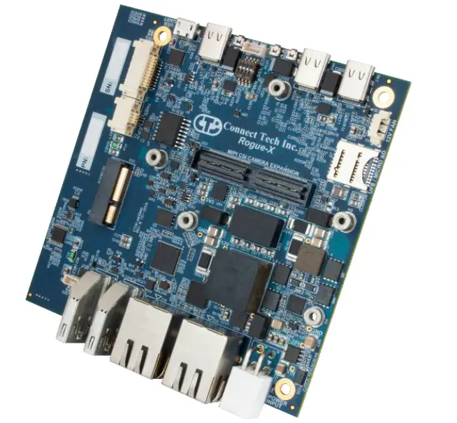
- Connect Tech’s Rogue-X (AGX103) is a full featured NVIDIA® Jetson AGX Xavier™ module carrier board. This carrier board for AGX Xavier™ is specifically designed for commercially deployable platforms, and has an extremely small footprint of 105mm x 105mm.
- The Rogue-X provides access to an impressive list of latest generation interfaces on the AGX Xavier™ while adding additional interfaces of 3x USB 3.1, 2x GbE, 2x HDMI and a locking Mini-Fit Jr. input power connector.
- Rugged camera add-on expansion boards will also be available for use with the Rogue-X to interface directly with the AGX Xavier™ high density MIPI CSI interfaces.
- Rogue-X builds upon the success of the Rogue by adding the ability to interface to two Ximea xiX Cameras. xiX is a trademark of Ximea GmbH.
Product Features and Specifications
| Specifications | |
| NVIDIA® GPU SoC Module Compatibility | NVIDIA® Jetson AGX Xavier™ |
| Networking | 2x Gigabit Ethernet (RJ45)
– 1 port from RGMII PHY (direct from module) – 1 port from a PCIe I210 MAC/PHY |
| Display Output | 2x HDMI 1.4a (Type A) |
| Camera Input – Ximea xiX | 2x PCIe Gen 2, 4 lane camera connectors (51 pin JAE FI-R connector) |
| Camera Input | 6x two lane MIPI CSI-2 or 4x four lane MIPI CSI-2
using a 120 pin (dev kit compatible) QSH expansion connection |
| USB | 3x USB 3.1 5Gbps/10Gbps (Type C – OTG mode 1 port)
(Note only 2 interfaces can be used at 10Gbps simultaneously) |
| Storage | 1x M.2 Key-M (NVMe) expansion slot (2 lane PCIe Gen 3) 1x microSD or UFS card slot |
| UART | 2x @3.3V UART1 and UART2
1x USB based Debug UART3 (microUSB AB connector) |
| I2C/SPI | 1x @3.3V I2C
1x @3.3V SPI |
| CAN Bus | 2x CAN 2.0b Isolated Ports |
| GPIO | 4x @3.3V GPIO (direct from module) |
| User Expansion | 1x M.2 Key-E expansion slot (1 lane PCIe Gen 3, USB 2.0) For WiFi/Bluetooth modules |
| Input Power | 9-19V DC Wide Input Power (4 pin Mini-fit Jr Connector)
14-19V required for full camera support with GPU under load |
| PCB / Electronics Mechanical Information | 105mm x 105mm |
| Operating Temperature (Carrier Board Only) | -40°C to +85°C (-40°F to +185°F) |
Part Numbers / Ordering Information
| Part Number | ||||
|
SKU |
AGX Xavier™ Module Included |
Heat Sink Options |
WiFi Bluetooth Options |
SSD Options |
|
AGX103 |
None |
None |
None |
None |
|
AGX103- 01 |
Yes |
None |
None |
None |
| AGX103- 02 |
Yes |
None |
None |
1x 1TB SSD
Installed |
| AGX103- 04 |
Yes |
None |
WiFi/BT Module Installed |
None |
| AGX103- 05 |
Yes |
None |
WiFi/BT Module Installed | 1x 1TB SSD
Installed |
| AGX103- 07 |
Yes |
CTI Active Thermal Installed |
None |
None |
| AGX103- 08 |
Yes |
CTI Active Thermal Installed |
None |
1x 1TB SSD
Installed |
| AGX103- 10 |
Yes |
CTI Active Thermal Installed | WiFi/BT Module Installed |
None |
| AGX103- 11 |
Yes |
CTI Active Thermal Installed | WiFi/BT Module Installed | 1x 1TB SSD
Installed |
|
AGX103- 13 |
Yes |
CTI Passive Thermal Installed |
None |
None |
| AGX103- 14 |
Yes |
CTI Passive Thermal Installed |
None |
1x 1TB SSD
Installed |
| AGX103- 16 |
Yes |
CTI Passive Thermal Installed | WiFi/BT Module Installed |
None |
| AGX103- 17 |
Yes |
CTI Passive Thermal Installed | WiFi/BT Module Installed | 1x 1TB SSD
Installed |
PRODUCT OVERVIEW
Block Diagram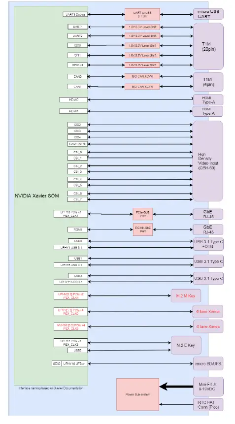
Board (Top Side) 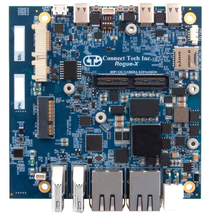
Board (Back Side) 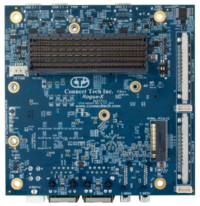
Connector Summary & Locations
| Designator | Description |
| P9 | Jetson AGX Xavier™ connector |
| J2 | M.2 M-Key (NVMe) connector |
| P8 | 5V Fan Connector – for Dev kit fan support |
| P4 | USB UART Debug Console connector |
| J3 | USB 3.1 device port and OTG programming port connector |
| J4A, J4B | USB 3.1 device ports |
| P3 | MISC I/O connector |
| P2 | CAN Bus Connector |
| P1 | MIPI Camera Expansion connector |
| P10 | M.2 E-Key connector |
| P11 | 12V Fan connector |
| P12 | External Switch Access connector |
| S7 | Micro SD or UFS Card Expansion port (Push/Pull) |
| P5A, P5B | HDMI Display output connectors |
| J1A, J1B | RJ45 GbE connectors |
| P6 | Input Power connector |
| P7 | RTC Battery connector |
| P13A, P13B | Ximea Camera connector |
| P14A, P14B | Ximea Camera IO connector |
Jumper Summary & Locations
| Designator | Description |
| S1 | Power Option control dip switches |
| S2 | CAN Bus Termination control dip switches |
| S3 | Power ON momentary switch |
| S5 | Force Recovery momentary switch |
| S6 | Reset momentary switch |
LED Summary
| Designator | Description |
| D6 | M.2 connector (J2A) activity |
| D9 | Input Power is good |
| D10 | System Power is good and system is powering on (booting up). In manual power on mode (via dip switch), this light will power on only after the power button has been pushed. Since the typical default mode is auto power on, the light will come on as on the system starts to boot. |
DETAILED FEATURE DESCRIPTION
LED Locations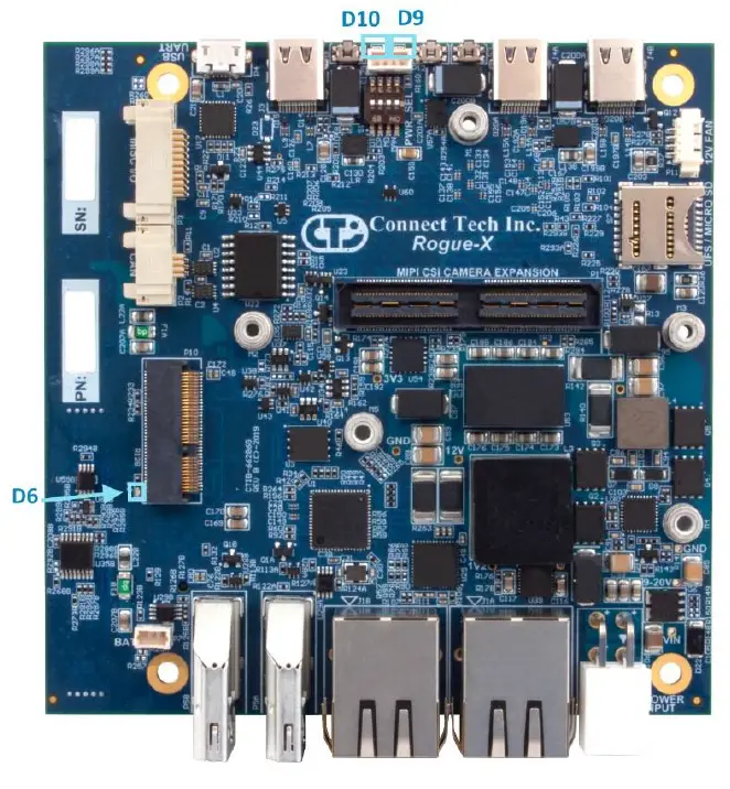
Connector and Switch Locations – Module Side 
- Jetson AGX Xavier™ Board-to-Board Carrier Connector
- With the NVIDIA® Jetson AGX Xavier™, the processor and chipset are implemented on the module.
Function NVIDIA® Jetson AGX Xavier™ Module Interface 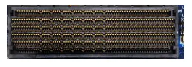
Location P9 Type Molex Mirror Mezz™ Connector Connector Part Number: 203456-0003 Manufacturer: Molex Mating Connector Same as above. Pinout Refer to NVIDIA® Jetson AGX Xavier™ System-on-Module datasheet and OEM design guide for pinout details
M.2 M-Key – NVMe
| Function | NVMe Storage (x2 PCIe Gen 3) | 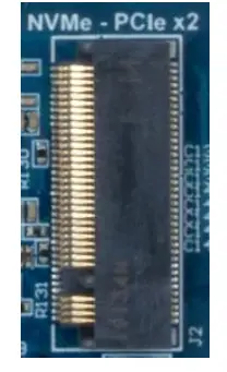 |
| Location | J2 | |
| Type | 2280 M.2 M-key 3.2mm mating height with M3 mounting standoff. | |
| Connector | Part Number: 1-2199119-5 Manufacturer: TE | |
| Mating Connector | N/A | |
| Pinout | M.2 Specification M-Key pin assignment. | |
| Notes | Interface is x2 PCIe Gen 3. SATA is not supported. PCIe based devices only. | |
Fan Connector (5V)
| Function | Fan control for Dev Kit | 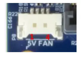 |
|
| Location | P8 | ||
| Type | 4 pin Panel-mate | ||
| Connector | Part Number: 53780-0470 Manufacturer: Molex | ||
| Mating Connector | Part Number: 51146-0400 (housing),
50641-8xxx (contact) Manufacturer: Molex |
||
| Pinout | Pin | Description | |
| 1 | GND | ||
| 2 | 5V Power | ||
| 3 | TACH from fan to module | ||
| 4 | PWM from module to fan | ||
| Notes | Installation note:
Fan connector must be installed before an NVMe card is installed in slot J2A (NVMe 1) to avoid interference.
This Fan connection is specifically for 5V fans ONLY, and will not properly work with a 12V Fan (see P11 below for 12V option).
This connector was removed on AGX113. |
||
CAN Bus TERM enable switch
| Function | Enable CAN Bus termination on CAN1 and CAN2 | 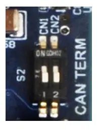 |
|||
| Location | S2 | ||||
| Type | 2 SPST dip switch | ||||
| Default | Product is shipped with both Terminations DISABLED. Only add the termination if the unit is an end point of any CAN Bus connection, otherwise leave disabled. | ||||
| Pinout | Switch | Description | ON | OFF | |
| S2-1 | CAN Bus 1 TERM Enable | 120 ohm | No TERM | ||
| S2-2 | CAN Bus 2 TERM Enable | 120 ohm | No TERM | ||
Ximea xiX Camera Connector (2 sites)
| Function | Ximea xiX Camera Control | 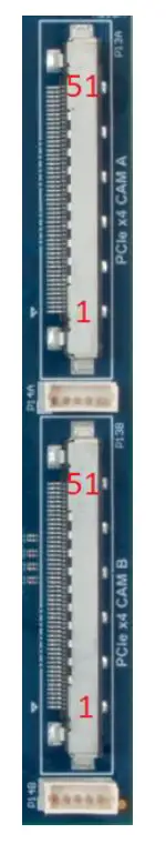
|
|
| Location | P13A/B | ||
| Type | 51 Position Receptacle Connector Surface Mount, Right Angle | ||
| Connector | Part Number: FI-RE51S-HF-R1500
Manufacturer: JAE Electronics |
||
| Mating Connector | Connector Only:
Part Number: FI-RE51HL Manufacturer: JAE Electronics
Cable Assembly: Part Number: JF08R0R0510x0UA where x = 2,3,4 for 20,30,40cm versions Manufacturer: JAE Electronics |
||
| Pinout | Connector Pins | Description | |
| 1,3,5,9,12,15,18,21,24,28,
31,34,37,40,43,47,49,51 |
GND | ||
| 2 | Opto-isolated Input 1 | ||
| 4 | Opto-isolated Input 2 | ||
| 6 | I/O 4 (LVTTL 3.3, 50uA) | ||
| 7 | I/O 3 (LVTTL 3.3, 50uA) | ||
| 8 | PCIe PERST# active low reset signal | ||
| 10 | PCIe Ref Clkp | ||
| 11 | PCIe Ref Clkn | ||
| 13 | PCIe Rx Lane 3p | ||
| 14 | PCIe Rx Lane 3n | ||
| 16 | PCIe Rx Lane 2n | ||
| 17 | PCIe Rx Lane 2p | ||
| 19 | PCIe Rx Lane 1n | ||
| 20 | PCIe Rx Lane 1p | ||
| 22 | PCIe Rx Lane 0n | ||
| 23 | PCIe Rx Lane 0p | ||
| 25,26,27 | 12V 0.9A PWR | ||
| 29 | PCIe Tx Lane 3p | ||
| 30 | PCIe Tx Lane 3n | ||
| 32 | PCIe Tx Lane 2p | ||
| 33 | PCIe Tx Lane 2n | ||
| 35 | PCIe Tx Lane 1n | ||
| 36 | PCIe Tx Lane 1p | ||
| 38 | PCIe Tx Lane 0n | ||
| 39 | PCIe Tx Lane 0p | ||
| 41 | Not Connected | ||
| 42 | Not Connected | ||
| 44 | Not Connected | ||
| 45 | I/O 2 (LVTTL 3.3, 50uA) | ||
| 46 | I/O 1 (LVTTL 3.3, 50uA) | ||
| 48 | Opto-isolated Output 2 | ||
| 50 | Opto-isolated Output 1 | ||
| Notes | Some lanes and pair polarity have been swapped but this is allowed per PCIe Spec.
Mating cable is rated to 0.3A per contact for 0.9A total |
||
Ximea IO Header
The Opto IO lines listed on the Ximea camera connector have also been broken out onto a separate connector
| Function | Ximea Opto-Isolated I/O | 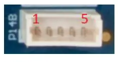 |
||
| Location | P14A/P14B | |||
| Type | 5 pin PicoBlade (vertical) | |||
| Connector PN | 53047-0510 – Manufacturer: Molex | |||
| Mating PN | 51021-0500 – Manufacturer: Molex | |||
| Pinout | Pin | Signal | Description | |
| 1 | Ximea Opto- isolated Output | Open Collector NPN | ||
| 2 | Ximea Opto- isolated Output | Open Collector NPN | ||
| 3 | Ximea Opto- isolated Input | <0.8V Low; 5V
High |
||
| 4 | Ximea Opto- isolated Input | <0.8V Low; 5V
High |
||
| 5 | GND | Ground / Return | ||
| Notes | Isolation is ONLY on the camera side.
By default, these lines are connected to an I2C I/O controller on the carrier board. Pins 1&2 are pulled up to 3.3V while pins 3&4 are pulled up to 5V
Custom orders have the ability to separate these lines from the carrier board and be directly connected to the camera where 24V operation would be allowed. |
|||
Connector and Switch Locations – User Interface Side 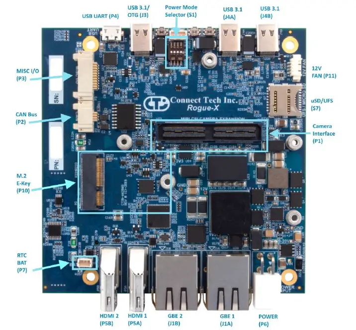
USB UART Debug console – Micro USB-AB
| Function | USB UART Debug console | 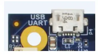 |
| Location | P4 | |
| Type | 5 Pin USB Micro AB connector | |
| Connector | Part Number: 47589-0001 Manufacturer: Molex | |
| Mating Cable | Any standard Micro USB to USB Type A | |
| Notes | This interface utilizes an FTDI USB to Serial device on board to allow access to the Jetson AGX Xavier™ Serial debug console using any Micro USB to USB A cable and any PC with a USB interface and serial terminal program. | |
USB 3.1/OTG Type C
| Function | USB 3.1 device port, OTG programming port | 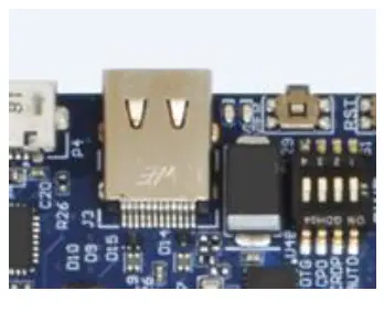 |
| Location | J3 | |
| Type | 24 Pin USB Type C | |
| Connector | Part Number: 632723300011 Manufacturer: Wurth | |
| Mating Cable | Any Standard Type C interface cable or device
** Note this port only supports USB devices, it does not include a display interface ** |
|
| Notes | This interface doubles as both a standard DFP (Downward facing port) USB 3.1 port to support USB 3.1 devices and the Jetson AGX Xavier™ Programming (flashing) interface port. The port is capable of up to USB 3.1 Gen 2 speeds in normal operation. The USB 2.0 portion of the interface doubles as the OTG programming port when the FORCE RECOVERY function is applied at startup. The power to the port is disabled so an external PC connection is possible to reprogram the module using Jetpack.
The maximum power available on this output is 1.5A @5V. |
|
USB 3.1 Type C
| Function | USB 3.1 device ports | 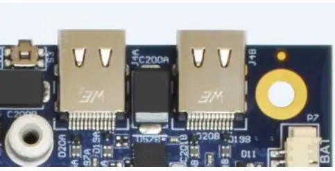 |
| Location | J4A, J4B | |
| Type | 24 Pin USB Type C | |
| Connector | Part Number: 632723300011 Manufacturer: Wurth | |
| Mating Connector | Any Standard Type C interface cable or device
** Note this port only supports USB devices, it will not work as a display interface ** |
|
| Notes | These interfaces are both standard DFP (Downward facing port) USB 3.1 Gen 2 capable ports used to support USB peripheral devices. Display devices or devices requiring 20V power modes are NOT supported.
These ports are capable up to USB 3.1 Gen 2 (10G) speeds in normal operation. Note that only any 2 interfaces can be used at 10Gbps simultaneously.
The power available from either of these ports is 3A @5V. However ONLY ONE port can be loaded at up to 3A at a time. Both will support simultaneous 1.5A loads. Overloading both of these ports will result in system power overload and the Rogue will shut down prematurely. |
|
RTC Battery
The Rogue allows for an external RTC battery to be connected. This battery should be a 3V DC battery, and it will hold settings including date and time. For further information about RTC battery selection and life time estimation, see Application Note 00009: https://connecttech.com/pdf/CTIN-00009.pdf
| Function | RTC Battery Connector | 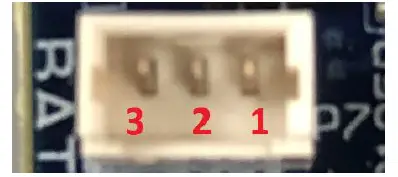 |
||
| Location | P7 | |||
| Type | 3 pin PicoBlade (vertical) | |||
| Connector PN | 53047-0310 – Manufacturer: Molex | |||
| Mating PN | 51021-0300 – Manufacturer: Molex | |||
| Pinout | Pin | Signal | Description | |
| 1 | +3V | RTC Battery Voltage Input | ||
| 2 | NC | No Connect | ||
| 3 | GND | Ground/Return | ||
MISC I/O Connector
| Function | 2x Serial (TTL), 1x I2C, 1x SPI, 4x GPIO | 
|
|
| Location | P3 | ||
| Type | 20 Pin | ||
| Connector | Part Number: T1M-10-GF-DH Manufacturer: Samtec | ||
| Mating Cable | S1SD-10-28-GF-xxx | ||
| Pinout | Connector Pins | Description | |
| 1 | UART1 TX | ||
| 2 | UART2 TX | ||
| 3 | UART1 RX | ||
| 4 | UART2 RX | ||
| 5 | I2C SCL | ||
| 6 | UART2 RTS# | ||
| 7 | I2C SDA | ||
| 8 | UART2 CTS# | ||
| 9,10,11,12 | GND | ||
| 13 | GPIO0 (GPIO12) | ||
| 14 | SPI CLK | ||
| 15 | GPIO1 (GPIO13) | ||
| 16 | SPI MOSI | ||
| 17 | GPIO2 (GPIO14) | ||
| 18 | SPI MISO | ||
| 19 | GPIO3 (GPIO17) | ||
| 20 | SPI CS# | ||
| Notes | This interface provides 3.3V capable generic I/O including:
· UART1 under /dev/ttyTHS0 UART2 under /dev/ttyTHS1 · I2C under i2c-0 · SPI under /dev/spidev0.0 · x4 GPIO under gpiochip2
For more information on I2C usage, please click here. For more information on GPIO usage, please click here. |
||
CAN Bus Connector
| Function | 2x Isolated CAN Bus | 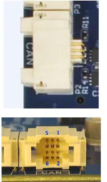
|
|
| Location | P2 | ||
| Type | 6 Pin | ||
| Connector | Part Number: T1M-03-GF-DH Manufacturer: Samtec | ||
| Mating Cable | S1SD-03-28-GF-xxx | ||
| Pinout | Connector Pins | Description | |
| 1 | CAN0_H | ||
| 2 | CAN1_H | ||
| 3 | CAN0_L | ||
| 4 | CAN1_L | ||
| 5 | GND_ISO | ||
| 6 | GND_ISO | ||
| Notes | This interface provides two isolated CAN Bus interfaces. | ||
CAMERA Expansion Connector
| Function | 8 MIPI CSI-2 Camera Interfaces + I2C and GPIO Control | ||||
| Location | P1 | ||||
| Type | 120 Pin QSH with M2.5 mounting standoffs | ||||
| Default | Part Number: QSH-060-01-L-D Manufacturer: Samtec | ||||
| Mating Connector | QTH | ||||
| Pinout | Pin # | Description | Pin # | ||
| 1 | CSI0_D0_P | CSI1_D0_P | 2 | ||
| 3 | CSI0_D0_N | CSI1_D0_N | 4 | ||
| 5 | GND | GND | 6 | ||
| 7 | CSI0_CLK_P | CSI1_CLK_P | 8 | ||
| 9 | CSI0_CLK_N | CSI1_CLK_N | 10 | ||
| 11 | GND | GND | 12 | ||
| 13 | CSI0_D1_P | CSI1_D1_P | 14 | ||
| 15 | CSI0_D1_N | CSI1_D1_N | 16 | 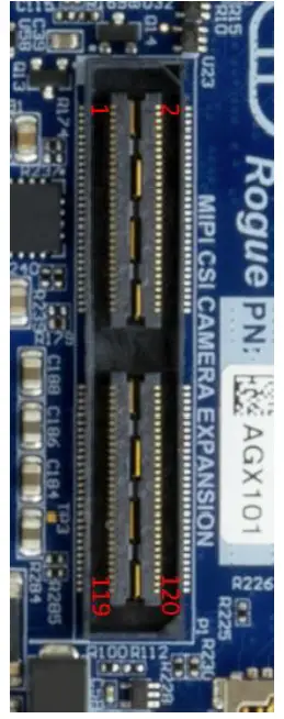 |
|
| 17 | GND | GND | 18 | ||
| 19 | CSI2_D0_P | CSI3_D0_P | 20 | ||
| 21 | CSI2_D0_N | CSI3_D0_N | 22 | ||
| 23 | GND | GND | 24 | ||
| 25 | CSI2_CLK_P | CSI3_CLK_P | 26 | ||
| 27 | CSI2_CLK_N | CSI3_CLK_N | 28 | ||
| 29 | GND | GND | 30 | ||
| 31 | CSI2_D1_P | CSI3_D1_P | 32 | ||
| 33 | CSI2_D1_N | CSI3_D1_N | 34 | ||
| 35 | GND | GND | 36 | ||
| 37 | CSI4_D0_P | CSI6_D0_P | 38 | ||
| 39 | CSI4_D0_N | CSI6_D0_N | 40 | ||
| 41 | GND | GND | 42 | ||
| 43 | CSI4_CLK_P | CSI6_CLK_P | 44 | ||
| 45 | CSI4_CLK_N | CSI6_CLK_N | 46 | ||
| 47 | GND | GND | 48 | ||
| 49 | CSI4_D1_P | CSI6_D1_P | 50 | ||
| 51 | CSI4_D1_N | CSI6_D1_N | 52 | ||
| 53 | GND | GND | 54 | ||
| 55 | +12V | +12V | 56 | ||
| 57 | +12V | +12V | 58 | ||
| 59 | CSI5_D0_P | CSI7_D0_P | 60 | ||
| 61 | CSI5_D0_N | CSI7_D0_N | 62 | ||
| 63 | GND | GND | 64 | ||
| 65 | CSI5_CLK_P | CSI7_CLK_P | 66 | ||
| 67 | CSI5_CLK_N | CSI7_CLK_N | 68 | ||
| 69 | GND | GND | 70 | ||
| 71 | CSI5_D1_P | CSI7_D1_P | 72 | ||
| 73 | CSI5_D1_N | CSI7_D1_N | 74 | ||
| 75 | I2C3_SCL | NC | 76 | ||
| 77 | I2C3_SDA | NC (PWM1) | 78 | ||
| 79 | GND | GND | 80 | ||
| 81 | +2.8V | +2.8V | 82 | ||
| 83 | +2.8V | NC | 84 |
| 85 | NC | NC (PWM2) | 86 | ||
| 87 | I2C2_SCL | CAM_MCLK3 | 88 | ||
| 89 | I2C2_SDA | CAM1_PWDN | 90 | ||
| 91 | CAM_MCLK2 | CAM1_RST# | 92 | ||
| 93 | CAM0_PWDN | CAM_MCLK4 | 94 | ||
| 95 | CAM0_RST# | NC | 96 | ||
| 97 | NC | NC | 98 | ||
| 99 | GND | GND | 100 | ||
| 101 | NC | 1.8V | 102 | ||
| 103 | NC | NC | 104 | ||
| 105 | I2C4_SCL | NC | 106 | ||
| 107 | I2C4_SDA | 3.3V | 108 | ||
| 109 | NC | 3.3V | 110 | ||
| 111 | NC | NC | 112 | ||
| 113 | NC | NC | 114 | ||
| 115 | GND | GND | 116 | ||
| 117 | NC | 3.3V | 118 | ||
| 119 | CAM_AVDD_EN | 3.3V | 120 | ||
| Notes | Only 6 of the CSI2 interfaces can be used at once in 2 lane configuration. Only 4 interfaces when using 4 lane configuration.
All non-CSI-2 I/O is 1.8V levels. CAUTION! – The 12V pins shown above differ from that of the NVIDIA® dev kit pinout. This 12V power can be used for Camera expansion requirements up to 2A @12V. |
||||
M.2 E-Key – WiFi and Bluetooth Expansion port
| Function | M.2 E-Key Expansion port | 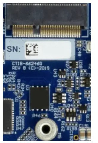 |
| Location | P10 | |
| Type | 75 Pin M.2 Connector with M2.5 mounting standoff | |
| Connector | Part Number: 2199230-4 Manufacturer: TE | |
| Mating Cable | N/A | |
| Pinout | As per the M.2 E-Key specification | |
| Notes | This port contains a x1 PCIe Gen 1 interface and one USB 2.0 interface. Support for M.2 2230 sizes only. | |
Fan Connector (12V)
| Function | Fan control for XHG306 | 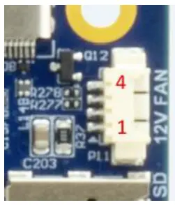
|
|
| Location | P11 | ||
| Type | 4 pin PicoBlade (right angled) | ||
| Connector | Part Number: 53261-0471 Manufacturer: Molex | ||
| Mating Connector | Part Number: 51021-0400 (housing),
50058-8000 (contact) Manufacturer: Molex |
||
| Pinout | Connector Pins | Description | |
| 1 | GND | ||
| 2 | 12V Power | ||
| 3 | TACH from fan to module | ||
| 4 | PWM from module to fan | ||
| Notes | Installation note:
This Fan connection is specifically for 12V fans ONLY. Forcing a connection of a 5V fan will result is a damaging the card and/or the fan. |
||
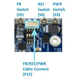
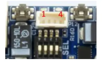
External Switch Access Connector
| Function | External Switch Access (Power, Reset, Force Recovery) |
|
|
| Location | P12 | ||
| Type | 4 pin PicoBlade (vertical) | ||
| Connector | Part Number: 53047-0410 Manufacturer: Molex | ||
| Mating Connector | Part Number: 51021-0400 (housing),
50058-8000 (contact) Manufacturer: Molex |
||
| Pinout | Connector Pins | Description | |
| 1 | GND | ||
| 2 | Force_Recovery_BTN# | ||
| 3 | Reset_BTN# | ||
| 4 | Power_BTN# | ||
| Notes | To activate any of the features, momentarily connect the signal the GND provided on the connector using momentary close switches only. | ||
Micro SD/UFS Card Expansion port
| Function | Micro SD or UFS Card Expansion | 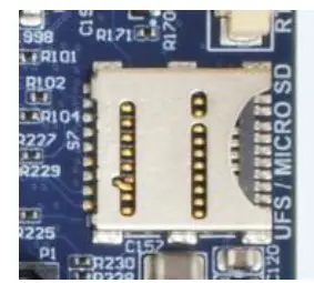 |
| Location | S7 | |
| Type | 19 Pin Multi card connector | |
| Connector | Part Number: 10101704J6#2A Manufacturer: Amphenol | |
| Mating Cable | N/A | |
| Pinout | As Per the micro SD and UFS Specification |
HDMI Video Outputs
| Function | HDMI Display Outputs | 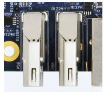 |
| Location | P5A, P5B | |
| Type | 19 Pin Multi card connector | |
| Connector | Part Number: 2013978-1 Manufacturer: TE | |
| Mating Cable | Standard HDMI cable | |
| Pinout | As per the HDMI Specification | |
| Notes | Outputs are capable of a resolution up to 3840×2160 @60Hz. Dual display is supported. | |
GBE RJ45 Connectors
| Function | GBE Network Connectivity | 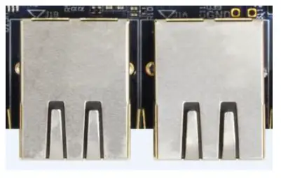 |
| Location | J1A, J1B | |
| Type | 8 pin RJ45 with integrated Magnetics | |
| Connector | Part Number: JXD0-0001NL Manufacturer: Pulse | |
| Mating Cable | Standard RJ45 Cat 5e | |
| Pinout | As per the IEEE-802.3 specification | |
| Notes | J1A comes direct from the AGX Xavier™ Module Ethernet port. J1B Comes from the local
carrier’s PCIe Intel I210 MAC/PHY. |
|
POWER Connector
| Function | Input Power | 
|
|
| Location | P6 | ||
| Type | 4 Pin Molex Mini-Fit Jr. | ||
| Connector | Part Number: 39-30-1042 Manufacturer: Molex | ||
| Mating Cable | ATX 4 pin Mini Fit Jr | ||
| Pinout | Connector Pins | Description | |
| 1 | GND | ||
| 2 | GND | ||
| 3 | +VIN | ||
| 4 | +VIN | ||
| Notes | Voltage Input Range 9V – 19V input range with input reverse polarity protection. Note that this connector is compatible with a 12V 4pin ATX Power supply connection.
14V minimum is required for full camera support with GPU under load. |
||
POWER Mode Select Switch
| Function | Power Mode selection | 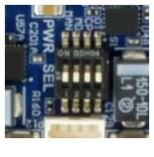 |
|||
| Location | S1 | ||||
| Type | 4 SPST dip switch | ||||
| Connector | Product is shipped with all switches OFF, the default is Auto On/Module Controlled mode. | ||||
| Mating Cable | Switch | Description | ON | OFF | |
| S1-1 | Auto or Manual Power On (MAN) | Manual Power On | Auto | ||
| S1-2 | Module Present Detect (MD) – Debug ONLY | DO NOT USE | Module controlled | ||
| S1-3 | Carrier Power On (CP) – Debug ONLY | DO NOT USE | Module controlled | ||
| S1-4 | OTG Port Power control (OT) – Debug ONLY | DO NOT USE | Auto | ||
| Notes | S1-1
AUTO Power ON Mode behavior
1) Upon applying power the system boots immediately.
2) Upon requesting a Software shutdown from the OS, the system will reboot after the shutdown completes without cycling power.
3) Upon a Power Button Event ( > 500 ms but < 10 secs) the system OS will prompt with the Restart/Shutdown pop-up menu (only applicable in the GUI).
4) Upon a Power Button Event ( > 10 secs) the system OS will prompt with the Restart/Shutdown menu (only applicable in the GUI). Note that the system will NOT shutdown.
Manual Power ON Mode behavior
1) Upon applying power the system will sit in standby, awaiting a ( > 500ms) Power Button Event.
2) Upon requesting a Software shutdown from the OS, the system will return to standby and await a new Power Button Event ( > 500ms).
3) Upon a Power Button Event while operating ( > 500 ms but < 10 secs) the system OS will prompt with the Restart/Shutdown menu (only applicable in the GUI).
4) Upon a Power Button Event while operating ( > 10 secs) the system will perform a hard shutdown immediately and return to the Power On standby state awaiting a new Power Button Event. |
||||
Push Button Switches
| Function | Power/Reset/Force Recovery Buttons | 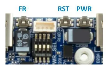
|
| Location | S3, S6, S5 | |
| Type | Momentary Push button micro switches | |
| Function | Power ON switch (S3): a press of >500ms when in manual mode will trigger system to power ON.
Reset Switch (S6): a press of >500ms will trigger a full system Reset.
Force Recovery (S5): No function during normal operation. Will place the AGX Xavier™ Module into Force Recovery Mode when held during power ON. |
TYPICAL INSTALLATION
- Ensure all external system power supplies are off.
- Install the Jetson AGX Xavier™ Module onto the Molex Mirror Mezz™ Connector. Be sure to follow the manufacturer’s directions for proper installation of mounting hardware, heatsink/heatspreader, and any other applicable requirements from the manufacturer.
- Install the necessary cables for application. At a minimum these would include:
- Power cable to the input power connector on the carrier
- HDMI video display cable
- Keyboard and mouse via USB
For additional information on the relevant cables, please see the Cables and Interconnects section of this manual.
- Connect the Power Cable to the Power Supply.
- Switch ON the Power Supply. DO NOT power up your system by plugging in live power.
SOFTWARE
For L4T (Linux for Tegra) BSPs and Software Support NVIDIA® Jetson™ AGX Xavier™ please follow this link: https://connecttech.com/resource-center/l4t-board-support-packages/
FORCE RECOVERY MODE
The USB 3.1/OTG Port (J3) of the Rogue can be used to reprogram the AGX Xavier™ from another host platform running NVIDIA® Jetpack™.
- Power down the system completely. The system power MUST be OFF, not in suspend or sleep mode.
- Connect the OTG USB port to another host device that will be supplying the new system file.
- Hold down the Force Recovery Button (S5) and then power the board.
- After three (3) seconds release the Recovery button.
- The AGX Xavier™ will show up on the host system USB list as a new NVIDIA® target device.
- After successfully updating the system software, power off the system. A clean power up will revert the OTG port back into host mode.
POWER CONSUMPTION
Below is the theoretical maximum stand-alone power consumption of the Rogue Carrier with the AGX Xavier™ Module installed. (System power)
| Theoretical Maximum System power | Watts |
| Theoretical absolute maximum total with AGX Xavier™ Module (30W Power Mode), 2x NVMe, 2x GbE, 3x USB 3.1 Gen 2 fully loaded (1x 3A, 2x 1.5A), 3x Camera (4 lane). | 75W |
The typical power consumption will vary depending on the application and use case.
| Theoretical Maximum System power | Watts |
| Idle, AGX Xavier™ (10W Power Mode), 1x display | 7.5W |
| Idle, AGX Xavier™ (10W Power Mode), 2x NVMe, 2x GbE, 1x WiFi/BT modules, dual display, 3x USB 3.1 Gen 2 to four port hubs , uSD Card, Serial Console. | 18W |
| AGX Xavier™ (30W Power Mode), 1x display running CUDA benchmarks | 42W |
| AGX Xavier™ (30W Power Mode), 2x NVMe, 2x GbE, 1x WiFi/BT modules, dual display, 3x USB 3.1 Gen 2 to four port hubs , uSD Card, Serial Console. Running CUDA, and system benchmarks. |
64W |
CABLES
| Part No. | Description |
| CBG310 | USB Type-C Male to Type-A Female Cable |
| CBG311 | USB Type-C Male to Type-A Male Cable |
| CBG247 | USB Micro-B Male to Type-A Male cable (UART Coms) |
| CBG312 | MISC IO Breakout Cable (Flying Leads) |
| CBG313 | CAN IO Breakout Cable (Flying Leads) |
| CBG136 | RTC Battery Cable Assembly |
| CKG064 | Rogue Full Cable Kit Including all of the above |
| MSG085 | AC/DC PSU Brick 19V/120W + adapter |
| CBG314 | Input Power Cable (Discrete Wire) – Included with every AGX103 Carrier. |
Cable drawings are available upon request. Send an email request to: support@connecttech.com
MECHANICAL DRAWINGS & MODELS
3D Model is located here: https://connecttech.com/ftp/3d_models/AGX103_3D_MODEL.zip
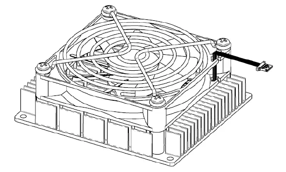
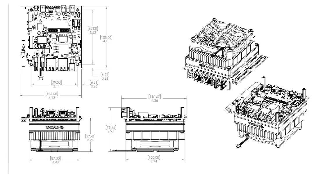
THERMAL OPTIONS
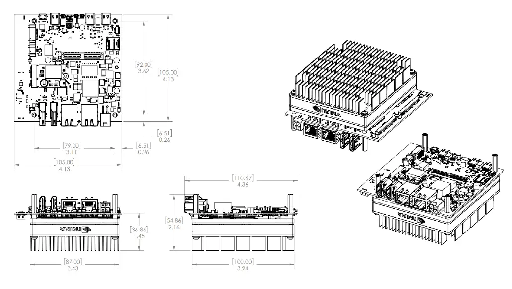
- Passive Heatsink (XHG305)

- Active Heatsink (XHG306)
Assembly drawings
- AGX103-01 Example (No Heatsink)

- AGX103-07 Example (Active Heatsink)
- AGX103-13 Example (Passive Heatsink)
Document: CTIM-00082
Revision: 0.04
Date: 2022-12-01
Rogue-X – NVIDIA® Jetson AGX Xavier™ Carrier Users Guide
www.connecttech.com
Documents / Resources
 |
CONNECT TECH Rogue-X NVIDIA Computer on Module [pdf] User Guide Rogue-X NVIDIA Computer on Module, Rogue-X, NVIDIA Computer on Module, Computer on Module, on Module, Module |


