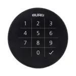
BURG Qleo.Code Electronic Combination Code Locks
Qleo. Code
- A : LED
- B : touchpad key
- C : handle
- D : battery compartment
- E : housing (handle)
- F : housing (lock)
- G : battery
- H : operating panel

General
The latest version of this guide is available at: www.burg.de
![]() Important notes:
Important notes:
- Please observe all important notes and read the entire operating manual before starting the configuration.
- Before putting the locking system into operation, refer to “Commissioning” on page 5.
- Master cards must be kept in a safe place. If lost, no further configurations can be made.
To the video: operation

To the video: assembly

To the video: battery change

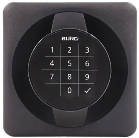
Factsheet
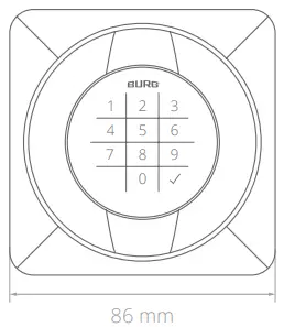
Front view
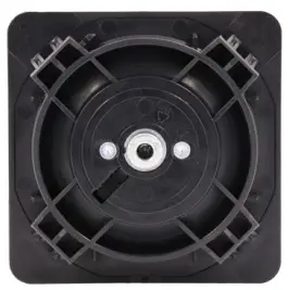
Back view
Technical Data
| Dimension | 86 mm x 86 mm |
| Battery1 | VARTA1 1/2 AAH-R (2x) 850 mAh, CR High Power |
| Locking cycles | approx. 30,000 |
| Material | housing: plastic stator: zamak |
| Humidity (rel.) | 10% – 80% |
| Temperature range | working temperature: 0°C to 55°C storage temperature: -20°C to 70°C |
| Degree of soiling | 2 |
| IP class | IP30 |
| Application areas | indoor |
| Mounting dimension | 72 mm x 72 mm |
| Max. door thickness | 0.7 mm to 1.2 mm |
| Lock attachment | clips |
| Cam type | B |
| Locking direction | left (90°), door hinge: DIN right right (90°), door hinge: DIN left |
| Mode | multi-user mode (default), private mode |
| No. of possible codes | 999,999 |
| Code length | 4- or 6-digit |
| No. of master codes | max. 1 |
| No. of codes | max. 50 (private mode) |
Scope of Delivery
- 1x locking system
- 1x retaining plate
- 1x type plate label
- 1x cam fixing screw2 (M6 x 12 mm)
- 1x two-point cam type B
Default Settings
| Mode | multi-user mode |
| Master code | 934716 |
| Code length | 4-digit |
| Locking | manually |
| LED locking indication | on |
| Confirmation code | off |
Optional Accessories
- battery (VARTA1 1/2 AAH-R)
- anti-twist protection (W-MSZ-01)
- opening pin
- cam type B (order-related)
Features
- ergonomists Handhabung und wertiges Design
- ergonomic handling and high-quality design
- external battery access and battery change
- integrated real-time clock (RTC) for individually definable time settings
- high-quality keyboard with tactile feedback
- easy to retrofit, e.g. to replace mechanical handle systems
- adjustable cam (in 90° steps)
Mounting Dimensions3

- The lock is approved for VARTA brand batteries. The use of other batteries may lead to malfunctions (s. point „battery note“).
- The use of a screw with a different length may cause damage to the lock.
- Mounting dimensions and templates (STEP files) for milling, punching or lasering can be requested from BURG.
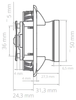
Product Dimensions
Front view
Side view
Functional Description
Mode: multi-user authorization (multi-user mode)
This mode is suitable for changing user groups where the locker is only used temporarily or once, e.g. in a sports facility. Codes are valid for a single locking process and are deleted from the lock when the compartment is reopened. The lock remains open until a new code locks the lock again.
Mode: fixed assigned authorization (private mode)
In this mode, a code is preset with which the lock can be operated. This mode is suitable for user groups where the usage rights should not change permanently, e.g. for an office cabinet.
The lock can only be operated with a stored code. Codes that are not stored are rejected by the lock.
Confirmation code (for multi-user mode)
To lock the lock, the code must be entered twice. The lock locks after the second entry. The second entry is made after the green LED flashes briefly. A simple code entry is sufficient to open the lock. This function can be turned on or off.
LED locking indication
If the lock is locked, the red LED flashes at short intervals. This function can be turned on or off.
Battery warning
If the battery voltage falls below a certain level (phase 1), the red LED lights up for a few seconds when the code is entered.
The lock can still be operated. If the voltage drops further (phase 2), the lock can no longer be locked. If the voltage falls into the critical range (phase 3), the lock can no longer be operated.
Master code
The master code authorizes the programming of the lock. In addition, the master code can unlock the lock independently of the set mode (emergency opening) and terminate the block mode. In multi-user mode, the code used for locking is deleted after the master code is entered.
Note: We recommend programming a private master code during commissioning.
Automatic locking (for private mode)
After unlocking, the lock locks automatically after a few seconds. The latch function allows the door to be closed by pressing slightly. This function can be turned on or off.
Block mode
If the code is entered incorrectly three times in succession, the lock locks for 45 seconds. The red LED flashes at short intervals.
The lock cannot be operated during this period. The block mode can also be ended by entering the master code.
Real-Time-Clock = RTC
The lock has an integrated real-time clock that enables time-related settings. If time-related settings are required, these must be specified when ordering. The functions are configured at BURG.
Automatic locking / unlocking (RTC function)
Automatic locking and unlocking takes place at set times. The times can be defined for each day of the week.
Usage period (RTC function)
The lock can only be used within a defined period of time. The lock cannot be operated outside this period. The usage period can be defined for each day of the week.
Closure duration (RTC function)
The locking duration defines the maximum period for which a lock may be closed from the time it is locked. The lock opens automatically once the locking period has expired. The locking duration can be defined for each day of the week.
LED Signals
Green LED (flashes briefly)
Acceptance of authorized codes and successful opening process / configuration step.
Green LED (flashing)
The lock is in configuration mode.
Red LED (flashing)
The lock is in the closed state or in block mode.
Red LED (flashes briefly)
Cancel an entry.
Red LED (flashes briefly after code entry)
Battery power decreases.
Red LED (8x flashing)
Rejection of unauthorized codes or incorrect entry during the configuration process.
Comissioning
First steps
- Remove the lock from packaging and open the battery compartment (for help, see page 10 “Battery change“).
- Insert the batteries according to the (+ / -) symbols. Wait the green and then the red LED. Close the battery compartment. The lock is now ready for use.
- Set private master code (chapter: Configuration, point 1: „Master code setting“).
![]() Configuration
Configuration
- Each configuration step is started by entering the master code, pressing the hook button twice and entering the corresponding digit.
- Entering the master code always begins by pressing the hook button twice and the digit 1. The entry is always ended by pressing the hook button once.
- Each configuration step is completed with the green LED flashing twice. Only then can the next configuration step be started.
- The red LED flashes 8 times to indicate that the configuration step has not been carried out correctly or the code / master code has not been entered correctly.
Master code setting
Up to 1 master code can be stored. The master code must be 6 digits long.
- Enter old master code:
✓✓ 1 Mastercode ✓
Wait for the green LED flashing twice. - Set new master code:
✓✓ 7 xxx xxx ✓
The green LED flashing twice confirms the successful process.
Mode change
When the mode is changed, all functions are reset to the factory setting. The master code is retained.
a) Multi-user mode
- Enter master code:
✓✓ 1 Mastercode ✓
Wait for the green LED flashing twice. - Set the mode:
✓✓ 5 1 ✓
The green LED flashing twice confirms the successful process.
b) Private mode
![]() When changing the mode to private mode, a private code must be set before use (chapter: Configuration, point 3b “Set the code”). If no code is set, the lock cannot be locked.
When changing the mode to private mode, a private code must be set before use (chapter: Configuration, point 3b “Set the code”). If no code is set, the lock cannot be locked.
- Enter master code:
✓✓ 1 Mastercode ✓
Wait for the green LED flashing twice. - 2. Set the mode:
✓✓ 5 0 ✓
The green LED flashing twice confirms the successful process. - Set the cod
Code configuration
a) Set the code length
![]() When the code length is changed, all codes stored in private mode are deleted (master code excluded).
When the code length is changed, all codes stored in private mode are deleted (master code excluded).
- Enter master code:
✓✓ 1 Mastercode ✓
Wait for the green LED flashing twice. - Set the code length (4-digit to default setting):
✓✓ 0 4 ✓ (4-digit)
✓✓ 0 6 ✓ (6-digit)
The green LED flashing twice confirms the successful process.
b) Set the code (private mode)
![]() Up to 50 codes can be stored. The code length is 4 or 6 digits, depending on the setting.
Up to 50 codes can be stored. The code length is 4 or 6 digits, depending on the setting.
- Enter master code:
✓✓ 1 Mastercode ✓
Wait for the green LED flashing twice. - Set the code:
✓✓ 3 xxxx (xx) ✓
The green LED flashing twice confirms the successful process.
Delete the code (private mode)
- Enter master code:
✓✓ 1 Mastercode ✓
Wait for the green LED flashing twice. - Delete the code:
✓✓ 9 xxxx (xx) ✓
The green LED flashing twice confirms the successful process.
Function setting
a) Automatic locking (private mode)
- Enter master code
✓✓ 1 Mastercode ✓
Wait for the green LED flashing twice. - Activate / deactivate mode:
✓✓ 6 1 ✓ (activate)
✓✓ 6 0 ✓ (deactivate)
The green LED flashing twice confirms the successful process.
b) Confirmation code (multi-user mode)
- Enter master code:
✓✓ 1 Mastercode ✓
Wait for the green LED flashing twice. - Activate / deactivate mode:
✓✓ 2 1 ✓ (activate)
✓✓ 2 0 ✓ (deactivate)
The green LED flashing twice confirms the successful process.
c) LED locking indication
- Enter master code:
✓✓ 1 Mastercode ✓
Wait for the green LED flashing twice. - Activate / deactivate mode:
✓✓ 8 1 ✓ (activate)
✓✓ 8 0 ✓ (deactivate)
The green LED flashing twice confirms the successful process.
Operation
Multi-user mode
a) Lock
![]() If the confirmation code is activated, the code used for locking must be entered twice in succession.
If the confirmation code is activated, the code used for locking must be entered twice in succession.
- Enter code:
xxxx (xx)
The green LED confirms the successful process.
b) Unlock
- Enter code:
xxxx (xx)
The green LED confirms the successful process.
Private mode
a) Unlock
- Enter code:
xxxx (xx)
The green LED confirms the successful process.
b) Lock (manually)
- Enter code:
xxxx (xx)
The green LED confirms the successful process.
c) Lock (automatically)
- When automatic locking is activated, the lock locks automatically after a few seconds. To close the door, press it shut and turn the knob back to the starting position (logo on top) until it clicks into place.
 Master Code Entry
- Entering the master code always begins by pressing the hook button twice and the digit 1. The entry is always ended by pressing the hook button once.
- In multi-user mode, the code used for locking is deleted after the master code is entered.
- Enter master code:
✓✓ 1 Mastercode ✓
The green LED flashing twice confirms the successful process.
Battery Change
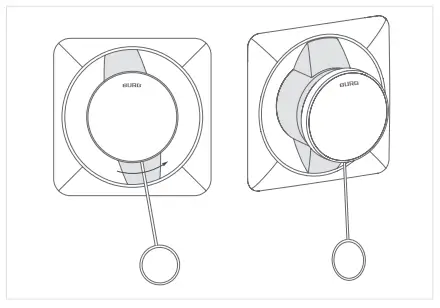
![]() The opening pin is required to change the battery. To open the battery compartment, only the housing (shown as a gray area in the sketches) needs to be turned.
The opening pin is required to change the battery. To open the battery compartment, only the housing (shown as a gray area in the sketches) needs to be turned.
- When disassembled, the lock must be held by the square housing (handle). When fitted, the lock does not need to be held in place.

- Carefully insert the opening pin into the closure hole underneath the operating panel until resistance is reached and press lightly.

- Hold the opening pin in position and turn the pin with the housing (shown as a gray area in the sketch) counterclockwise by approx. 10°. The operating panel is not rotated during this process.
- Remove the opening pin and pull the operating panel forwards.

- Remove the battery compartment cover. Replace the batteries according to the (+/-) symbols and reinsert the battery compartment cover.
- Push back the operating panel. Carefully turn the housing (shown as a gray area in the sketches) clockwise until it clicks into place.
Assembly Note
Please observe the following instructions before starting the assembly.
- The cam is only attached after the handle has been fitted.
When the cam is attached, the embossed logo faces away from the lock and is therefore visible from behind:

- If the electronic lock is installed in the European Economic Community (EU and EFTA), the enclosed type plate must be clearly visible, legible and permanently affixed to the cam (on the back of the door). Otherwise the product does not comply with the safety standard of the RED (Radio Equipment Directive).

Conformity / Certification
![]() CE Declaration of Conformity
CE Declaration of Conformity
Hereby, BURG Lüling GmbH & Co. KG declares that the radio equipment, type Qleo. Code, is in conformity with Directives 2014/30/EU and 2011/65/EU. The full text of the EU Declaration of Conformity can be found at the following link:
https://www.burg.de/files/downloads/Declaration-of-Conformity/BURG_DoC_QleoCode_EN.pdf
FCC Compliance
This equipment has been tested and found to comply with the limits for a Class B digital device, pursuant to Part 15 of the FCC Rules. Operation is subject to the following two conditions:
- This device may not cause harmful interference, and
- this device must accept any interference received, including interference that may cause undesired operation.
CAUTION: The user is not permitted to change or modify this class B equipment unless expressly authorized to do so by the party responsible for ensuring compliance. Changes or modifications could void the user‘s authority to operate the equipment.
IC Compliance
This class B device complies with Industry Canada RSS standard ICES-003. Operation is subject to the following two conditions:
- This device may not cause interference, and
- this device must accept any interference, including interference that may cause undesired operation of the device.
Changes or modifications not expressly approved by the party responsible for compliance could void the user‘s authority to operate the equipment.
US Representative (company stamp or address):
Guarantee and Warranty
The warranty is subject to the statutory provisions. If you have any questions, please contact a specialist dealer or use the contact details below. Spare parts can be found at specialist dealers or at: www.burg.shop
Cleaning and Care Instructions
Remove the batteries before cleaning the appliance. Carefully clean the surfaces of the appliance with a damp, clean cloth. Chemical cleaning agents must not be used. Do not allow dust or liquids to enter the device.
Disposal and Battery Note
EU Directive 2012/19/EU regulates the proper take-back, treatment and recycling of used electronic devices.
![]() Every consumer is legally obliged to dispose of batteries, rechargeable batteries or electrical and electronic devices (“old devices”) that are powered by batteries or rechargeable batteries separately from household waste, as they contain harmful substances and valuable resources. They can be disposed of at an approved collection or take-back point, e.g. a local recycling center. Old appliances, batteries and rechargeable batteries are accepted there free of charge and recycled in an environmentally friendly and resource-saving manner. Old electrical appliances, used batteries or rechargeable batteries can also be returned to us. The return shipment must be sent with sufficient postage to the address below. The following symbol on waste electrical equipment, batteries or rechargeable batteries indicates that they must not be disposed of with household waste:
Every consumer is legally obliged to dispose of batteries, rechargeable batteries or electrical and electronic devices (“old devices”) that are powered by batteries or rechargeable batteries separately from household waste, as they contain harmful substances and valuable resources. They can be disposed of at an approved collection or take-back point, e.g. a local recycling center. Old appliances, batteries and rechargeable batteries are accepted there free of charge and recycled in an environmentally friendly and resource-saving manner. Old electrical appliances, used batteries or rechargeable batteries can also be returned to us. The return shipment must be sent with sufficient postage to the address below. The following symbol on waste electrical equipment, batteries or rechargeable batteries indicates that they must not be disposed of with household waste:
Important notes on the use of batteries:
- The use of high-quality brand batteries is essential for the correct functioning of the locking system. BURG locking systems are approved ex works for the specified industrial batteries of the VARTA brand. The use of batteries of other brands can lead to a reduced number of possible locking cycles as well as to limited functionality and functional problems, as experience has shown that batteries of other brands even with the same specifications have different performance characteristics. BURG does not guarantee the functionality of the locking system when using batteries of a brand other than those specified above.
- If both batteries are removed at the same time when changing the batteries or over a longer period of time, settings relating to the integrated real-time clock (RTC) will be lost.
- The battery may explode or release flammable gases if it is handled incorrectly, destroyed or the wrong type of battery is used. Do not recharge the battery, disassemble it, expose it to extremely high temperatures or throw it into a fire. Batteries containing harmful substances are labeled with abbreviations for the substances cadmium (Cd), mercury (Hg) and lead (Pb).
If the lock is not used for a longer period of time, the batteries must be removed.
Contact
Volmarsteiner Str. 52
58089 Hagen (Germany)
+49(0)2335 6308-0
info@burg.de
www.burg.de


Documents / Resources
 |
BURG Qleo.Code Electronic Combination Code Locks [pdf] Instruction Manual Qleo.Code Electronic Combination Code Locks, Qleo.Code, Electronic Combination Code Locks, Combination Code Locks, Code Locks |