BRE MK60E5 Haltech CAN Gateway Instruction Manual

Congratulations on your purchase! Here you will find the easy button for integrating your MK60E5 ABS with your Haltech ECU. Before we get too far, there is one thing that needs to be mentioned:
******************************************************************************************
This product is for off-road use ONLY. Absolutely no warranty or liability is provided, implied, or assumed for anything other than the device itself. This device simply translates data from the ABS Module into a format that can be read by Haltech ECUs. What you do with that data is up to you. Use at your own risk.
******************************************************************************************
Depending on which kit you purchased, you will get either a mating connector and terminals or a Nearly PnP wire harness. This installation manual will apply to both.

2/7 CAN 1 is to be connected to Haltech CAN
3/6 CAN 2 is to be connected to MK60E5 PT-CAN (Pins 15 and 30 on the MK60E5 module)
Power should come from an ignition switched power source. The normal Haltech CAN wiring is perfect for this.
For the Nearly PnP kit, the only connections that will need to be made are the CAN2 to MK60E5 PT- CAN connection splices. The White wire will connect to PT-CAN High, while the Green will connect to PT- CAN Low. These connections can be found at Pins 30 and 15 on the main MK60E5 connector or pins 6 and 14 on your MK60E5 Diagnostic (OBD2) connector. The Haltech CAN connector is ready to plug in to your Haltech CAN bus!
Once all connections have been made, open up your NSP software and connect to the ECU. Scroll down to Haltech CAN System and enable PD16 Box C and PD16 Box D. Once this is done, reboot the ECU and proceed with sensor calibration. You should now see the devices as Online if selected on the function tree.
Wheel Speed Sensor Configuration
These numbers match the MK60E5 output to the Haltech input, but will need to be adjusted. Follow the standard Haltech procedure for speed sensor calibration.


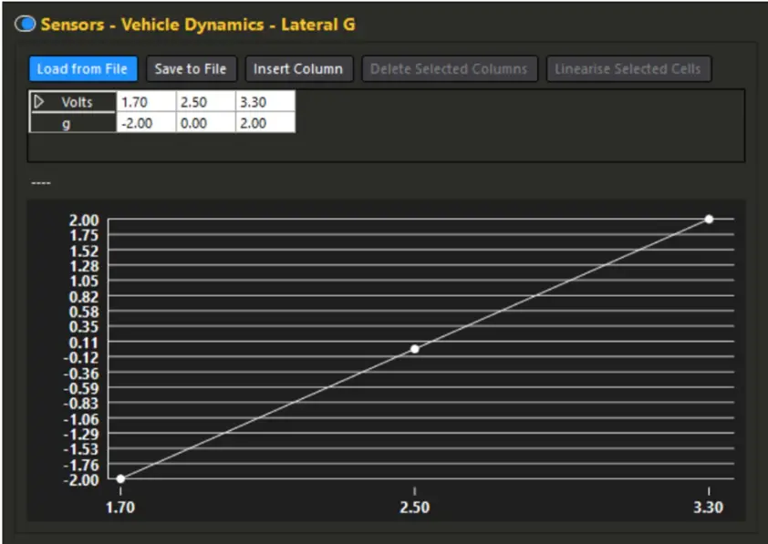
Vehicle Dynamics Sensors Configuration
The Lateral G calibration is confirmed accurate, though the Yaw Rate calibration is experimental at this stage. Comparison against a known source is recommended if using the sensor for any kind of controls.


Brake Pressure Sensors Configuration
This section is currently untested but should be working. Compare the Haltech data against readings in the BMW Diagnostic Software INPA before using for anything critical.
Haltech does not have pre-defined channels for individual brake pressure sensors, so these must be setup as Generic Sensor Inputs. Under the Generics section, enable 4 Generic Sensors. All of the calibration and configuration will be the same for each channel, only the input will vary. Sensory Type to Pressure, Device Input Type to Analog Voltage.
Overall Brake Pressure is a 5th channel provided by the MK60E5 and is recommended to be assign to the Brake Pressure Front channel in the Haltech software. Same calibration and configuration as the individual channels. This one is available under the normal Sensors section.
Front Left – PD16 “D” AVI 1
Front Right – PD16 “D” AVI 2
Rear Left – PD16 “D” AVI 3
Rear Right – PD16 “D” AVI 4
Overall – PD16 “C” AVI 3

Fault Indicator Setup
In addition to the various sensor channels, the Fault Indicator is also available for use. This channel will be configured on PD16 “C” AVI 4. It has the following states:
0 – No Fault
1 – Fallback
2 – Malfunction
3 – Invalid Data
Typically, the only states you should see are 0 or 2. The next few screenshots will show input configuration. This creates a channel that can now be used to trigger either a warning message on your dash, or an external warning light using a Generic Output. Shown in the screenshots on the next page will be a generic output example to trigger a warning light.


Documents / Resources
 |
BRE MK60E5 Haltech CAN Gateway [pdf] Instruction Manual MK60E5 Haltech CAN Gateway, MK60E5, Haltech CAN Gateway, CAN Gateway, Gateway |