BrainChild QS0MCT1A MCT Multi Loop Controller
Specifications
- Model: MCT Ver: QS0MCT1A
- Type: 1/4 DIN Multi-Loop Controller
- Interface: Touch Screen
Product Usage Instructions
Install Process Control/Limit Modules
- Select a slot for the module and remove the empty slot cover.
- Set DIP switch on the module for the required input type.
- Insert the module into the slot and secure it in place using retention screws.
Installation and Mounting
- Cut a proper size opening in the panel and insert the MCT controller through the front panel cutout.
- Insert curved tab of retention brackets into notches in the MCT and tighten screws evenly to secure it in place.
Connections and Wiring
- Connect input/output wiring to the installed PCM/HLM modules following the connection diagrams provided.
- Connect the MCT to a network or PC via its serial communication interface (optional).
Configure The MCT For Use
Switch between Operation/Configuration Modes as needed to set up and configure the MCT for use.
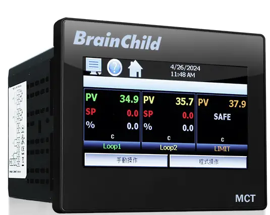
MCT – 1/4 DIN Multi-Loop Controller A 1/4 DIN multi-loop controller that operates like your favorite smartphone or tablet
Easy To Use Touch Screen Interface
- Follow the steps in this quick start guide to set up and begin using your MCT controller.

Hardware Recommended
ToolsHardware Recommended Tools
- Hardware

- PCM (process control module)
- Note: at least 1 required

- HLM (high limit module)
- Note: optional

Accessory
- Retention bracket for mounting

Tools
- Small Phillips screwdriver

- Small flathead screwdriver

- Wire and wire stripper (maximum 14awg)
Installation
Install Process Control/ Limit Modules
- A. Select a slot for the module.
- B. Loosen screws; remove empty slot cover

- C. Set DIP switch on module for required input type.
- HLM 0-1V and 0-5V/1-5V input types are special order. HLMs ordered with either input type cannot be configured or programmed for any other type.

- D. Insert module into slot while observing card orientation and secure module in place using retention screws from slot cover.

Installation and Moniting
- A. Cut proper size opening in panel.

- B. Insert MCT controller through front panel cutout.

- C. Insert curved tab of retention brackets(C) into notches in the top, bottom and sides of the MCT(B) and tighten screws evenly in order to secure the MCT in place.

Connections and Wiring
- A. Connect power using 14 AWG copper conductors rated for mini mum 90°C.To make a connection, strip ¼” of insulation off the end of the wire, turn the connector screw counter-clockwise until the gap is wide open, insert the wire all the way in, and turn the screw clockwise until it’s tight (maximum torque rating = 0.51 N-m).

- B. Input/output control wiring: Connect input/output wiring to the installed PCM/HLM modules. PCM connection diagram provided on left side of MCT. HLM connection diagram provided on right side of MCT.

- C. Communication interfaces: Connect the MCT to a network and or PC via its serial communication interface (optional).

Note:
- High voltage units (90 to 250 VAC) are equipped with an orange power connector. Low voltage units (11 to 26 VAC/DC) are equipped with a green power connector.
Note:
- A communication connection is not required to set up or use your MCT.
Note:
- Removable connectors make wiring easy. Remove the connector, attach your wires and simply plug it back in.

Note:
- Upon application of power, if the MCT does not come on within 2 seconds, remove power. Check wiring to insure proper connections and try to power up again. An Internal fuse will prevent damage for over-voltage conditions; however, it isn’t guaranteed.
Configure The MCT For Use
4-1 Switch between Operation/ Configuration Modes
- Configuration mode supports English interface only
- Operating mode supports multi-language. To change language, go to Configuration mode > Offline setting.
To turn off data recording
- Apply main power to the MCT and allow the unit to start up (Image A).
- Press
 the menu icon and select Data > Data (Image a/b). Turn off the green light on the upper-right corner. Press homepage
  the home icon to exit to (Image b).
To enter the Offline setting:
- Press the menu icon to access and select Device > Settings (Image c).

To change language interface:
- In offline mode, again press the Menu and select Set > Language (Image e). Choose your desired language to ON. Tap <Save> (Image f). Tap <OK> at the prompt.
- Press the menu icon > System to continue offline setting (Image G) or
- press the home icon to exit to operation Home. (Image A).

Configure parameters of the controller:
To configure the unit manually:
- In offline mode, press the menu icon and select ‘Exit’ from the ‘System’ menu (Image G). *Menu> System > Exit
- On the Exit Application screen press the second choice ‘Exit application.
(configuration mode startup)‘ button to quit the runtime (Image H). Tap <Yes> at the prompt to exit to reboot into the Configurator application.(Image B)
- Begin by pressing the menu icon and select ‘Control Setup’ from the ‘Setup’ menu. Set the control type according to the installed PCMs/ HLMs (Image I) * Configuration mode supports English interface only
- Once the control type is set, navigate to the Loop Configuration by selecting it from the ‘Setup’ menu (Image J/ K). * Menu > Setup > Loop Configuration

- Configure the loop by selecting the various settings form the list and entering the required values (Image L).

- Continue the process for other loops and limit (if installed). (Image M)
- Personalize the interface by removing features not required by selecting ‘Functions’ from the ‘Startup’ menu and turning the required options on or off. (Image N) *Menu > Startup > Functions

- Once all settings have been completed, select ‘Exit” from the ‘File’ menu. (Image O). Once the Configurator window has been closed, cycle power to the MCT to complete the configuration process. (Image P)

Auto configure parameters by importing files
To import an existing configuration file:
Follow steps 1-2. Cycle power to the MCT to operation mode. (P)
- Press the menu icon and select Data > Data (Image Q). Turn off the green light on the upper-right corner. Press the Home to exit. (Image R)
- Press the menu icon and select Device > Settings (Image S). Press the menu icon again and select Offline > Offline (Image T). Tap <Yes>.

- In offline mode, press the menu icon > System > Configuration (U).
- To import a configuration from a USB memory stick, first insert the USB memory device containing the desired configuration file into the USB port of the MCT. (Image V)

- Press the ‘Load Configuration’ file button, open the desired file and allow cthe configuration to load (Image V/ W).
- Once the import is completed, cycle power to the MCT to complete the configuration process. (Image X)

| File | |
| 1 Exit | 3 Loop Address Utility |
| 2 About | 4 Smart IO Comms Utility |
| Setup | |
| 1 Control Setup | |
| Soft Alarms, Monitor Points, Math/Logic, Outputs Off on Input Error | |
| 2. Loop Configuration | |
| 2.1 TagName | 2.21 Output 4 Function |
| 2.2 Input Type | 2.22 Output 4 Failure Transfer |
| 2.3 Input Units | 2.23 Output 4 Low/High Limit Values |
| 2.4 Decimal Point | 2.24 Output 4 Retransmit Low/High Scale |
| 2.5 Input Low/High Scale | 2.25 Alarm (1-3) Function |
| 2.6 Input Filter | 2.26 Alarm (1-3) Mode |
| 2.7 Event Input Function | 2.27 Alarm (1-3) Indication |
| 2.8 Event Input Alarm Message/Annotation | 2.28 Alarm (1-3) Setpoint |
| 2.9 Low/High Limit Setpoint | 2.29 Alarm (1-3) Hysteresis |
| 2.10 Output 1 Function | 2.30 Alarm (1-3) Delay |
| 2.11 Output 1 Failure Transfer | 2.31 Setpoint at Start of Automatic Program |
| 2.12 Output 1 ON-OFF Control Hysteresis | 2.32 Setpoint at End of Automatic Program |
| 2.13 Output 1 Cycle Time | 2.33 Power Fail Recovery |
| 2.14 Output 1 Low/High Limit Values | 2.34 Communication Mode |
| 2.15 Output 2 Function | 2.35 Loop Mode |
| 2.16 Output 2 Failure Transfer | 2.36 Ramp Rate Operation |
| 2.17 Output 2 Cycle Time | 2.37 Ramp Rate Down Low/Upper Limit |
| 2.18 Output 2 Low/High Limit Values | 2.38 Ramp Rate Up Low/Upper Limit |
| 2.19 Output 3 Function | 2.39 Setpoint 2 Format |
| 2.20 Output 3 Failure Transfer | 2.40 Setpoint 2 |
| 3. Limit Configuration | |
| 3.1 TagName | 3.12 Output 2 Function |
| 3.2 Input Type | 3.13 Alarm Function |
| 3.3 Input Units | 3.14 Alarm Mode |
| 3.4 Decimal Point | 3.15 Alarm Indication |
| 3.5 Input Low/ High Scale | 3.16 Alarm Setpoint |
| 3.6 Input Filter | 3.17 Alarm Hysteresis |
| 3.7 Output 1 Function | 3.18 Alarm Failure Transfer |
| 3.8 Output 1 Hysteresis | 3.19 Event Input Function |
| 3.9 Lower/ Upper Limit of High Setpoint | 3.20 Display Format |
| 3.10 Lower/ Upper Limit of Low Setpoint | 3.21 Restart Mode |
| 3.11 High/ Low Limit Setpoint | |
| 4 Monitor Configuration | |
| 4.1 Tagname | 4.4 Decimal Point |
| 4.2 Input Type | 4.5 Input Low/High Scale |
| 4.3 Input Units | |
| 5 Soft Alarm Configuration | |
| Alarm source, Alarm type, Inhibit, Silent, Email, Ringback, Alarm Setpoint, Hysteresis, Delay | |
| 6 Math/Logic Configuration | |
| 6.1 Entering a Math/Logic Equation | 6.2 Math/Logic Equation Examples |
| Options | |
| 1 Cascade Control | |
| Disabled, Process, Deviation, Ratio | |
| 2 Expansion IO | |
| 2.1 Input (8-23) Function | 2.3 Input Low/High Scale |
| 2.2 Input (8-23) Alarm Message/Annotation | |
| 3 Event Timer | |
| Event timer option, Power fail mode, Alarm on completion, Email/SMS on Completion | |
| Startup | |
| 1 Functions | 2 Startup View |
| Tagnames | |
| 1 Alarm Name | 3 Custom Name\ Address |
| 2 Event Names | |
more info
assistance contact Tech Support:
- service@brainchild.com.tw
- 886-2-2786-1299
- http://www.brainchildtw.com
FAQ
- Q: Do I need a communication connection to use the MCT?
- A: No, a communication connection is not required to set up or use your MCT.
- Q: What should I do if the MCT does not power up?
- A: If the MCT does not come on within 2 seconds of applying power, remove power, check wiring for proper connections, and try powering up again. An internal fuse will prevent damage for overvoltage conditions.
Documents / Resources
 |
BrainChild QS0MCT1A MCT Multi Loop Controller [pdf] User Guide QS0MCT1A MCT Multi Loop Controller, QS0MCT1A, MCT Multi Loop Controller, Multi Loop Controller, Loop Controller |


