![]() BL206 BL206Pro
BL206 BL206Pro
User Manual

Version:V1.2
Date:2023-10-24
Shenzhen Beilai Technology Co.,Ltd
Website:https://www.bliiot.com
BL206 Distributed Distributed Input Output Ethernet
Preface
Thanks for choosing BLIIoT Distributed I/O. These operating instructions contain all the information you need for operation of BL206 and BL206 Pro.
Copyright
This user manual is owned by Shenzhen Beilai Technology Co., Ltd. No one is authorized to copy, distribute or forward any part of this document without written approval of Shenzhen Beilai Technology. Any violation will be subject to legal liability.
Disclaimer
This document is designed for assisting user to better understand the device. As the described device is under continuous improvement, this manual may be updated or revised from time to time without prior notice. Please follow the instructions in the manual. Any damages caused by wrong operation will be beyond warranty.
Revision History
| Update Date | Version | Description | Owner |
| 2021-10-13 | V1.0 | First Edition | ZLF |
| 2022-07-01 | V1.1 | Add Profinet, EtherCAT protocol, add platform, logic control functions |
HYQ |
| 2023-07-27 | V1.1 | Change Model name | HYQ |
| 2023-10-24 | V1.2 | Add BL203, BL206, BL207 description |
HYQ |
| 2023-10-24 | V1.2 | User manual split by model | HYQ |
Product Introduction
1.1 Overview
The BL206Pro EdgeIO controller is a data acquisition and control system based on a powerful 32-bit microprocessor design with Linux operating system, supports Modbus, MQTT, OPC UA protocols for quick access to on-site PLC, DCS, PAS, MES, Ignition, and SCADA as well as ERP systems, as well as quick connectivity to a number of cloud platforms such as AWS Cloud, Thingsboard, Huawei Cloud, and Ali Cloud.
The I/O system supports programmable logic control, edge computing, and customized applications, it is widely applicable to a variety of IIoT and industrial automation solutions.
The BL206Pro distributed I/O system consists of 3 parts: Controller, I/O modules and terminal module.
 The communication between the I/O and the field devices (eg PLC) takes place via the Ethernet port of the controller, and the communication between the controller and the I/O modules takes place via the local bus. The two Ethernet ports are internally integrated with a switch function, which can establish a linear topology without the need for additional switches or hubs.
The system needs to use the power module to provide 24VDC system voltage and 24VDC field voltage. Since two independent power supplies are used, the field voltage input interface and system voltage input interface of BL206Pro controller are electrically isolated from each other.
When assembling fieldbus node modules, each I/O module can be arranged in any combination, and it is not required to be grouped by module type.
A terminal module must be plugged into the end of a fieldbus node to ensure correct data transmission.
1.2 Typical Application
High reliability, easy expansion, easy setting, and convenient network wiring, these capabilities let users efficiently adapt the BL206Pro I/O system to a variety of complex industrial solutions.
The I/O system is widely applicable to a variety of industrial solutions, such as Internet of Things, smart factories, smart cities, smart medical care, smart homes, smart transportation, data center power environment monitoring, electric power, oil monitoring, automobiles, warehousing and logistics and other industries.
1.3 Features
- Each I/O system can have a maximum of I/O 32 modules.
- Support Modbus, MQTT, OPC UA protocols.
- Support Alibaba Cloud, Huawei Cloud, AWS Cloud, Thingsboard, Ignition, etc.
- Support programmable logic control, edge computing.
- The field side, the system side and the bus side are electrically isolated from each other.
- Support 2 X RJ45 interface, integrated switch function, can establish line topology, without the need for additional switches or hubs.
- Convenient wiring connection technology, screw-free installation.
1.4 Model List
| Description | Model | Channel | Type |
| Modbus-TCP I/O Coupler | BL200 | / | / |
| Profinet I/O Coupler | BL201 | / | / |
| EtherCAT I/O Coupler | BL202 | / | / |
| Ethernet/IP I/O Coupler | BL203 | / | / |
| OPC UA EdgeIO Controller | BL205 | / | / |
| MQTT EdgeIO Controller | BL206 | / | MQTT |
| MQTT+OPC UA+Modbus TCP | BL206Pro | / | MQTT, OPC UA, MQTT |
| BACnet/IP I/O Coupler | BL207 | / | / |
| BACnet/IP+MQTT+OPC UA | BL207Pro | / | / |
| 8CH DI | M1081 | 8 | NPN (low level trigger) |
| 8CH DI | M1082 | 8 | PNP (high level trigger) |
| 16CH DI | M1161 | 16 | NPN (low level trigger) |
| 16CH DI | M1162 | 16 | PNP (high level trigger) |
| 4CH DO | M2044 | 4 | Relay |
| 8CH DO | M2081 | 8 | PNP |
| 8CH DO | M2082 | 8 | NPN |
| 16CH DO | M2161 | 16 | PNP |
| 16CH DO | M2162 | 16 | NPN |
| 4CH AI Single-Ended | M3041 | 4 | 0-20mA/4-20mA |
| 4CH AI Single-Ended | M3043 | 4 | 0-5V/0-10V |
| 4CH AI Differential | M3044 | 4 | 0-5V/0-10V |
| 4CH AI Differential | M3046 | 4 | ±5V/±10V |
| 4CH AO | M4041 | 4 | 0-20mA/4-20mA |
| 4CH AO | M4043 | 4 | 0-5V/0-10V |
| 4CH AO | M4046 | 4 | ±5V/±10V |
| 2CH RTD | M5021 | 2 | 3Wire PT100 |
| 2CH RTD | M5022 | 2 | 3Wire PT1000 |
| 2CH RTD | M5023 | 2 | 4Wire PT100 |
| 2CH RTD | M5024 | 2 | 4Wire PT1000 |
| 4CH TC | M5048 | 4 | TC(B/E/J/K/N/R/S/T) |
| 2CH RS485 | M6021 | 2 | RS485 |
| 2CH RS232 | M6022 | 2 | RS232 |
| 1CH RS485, 1CH RS232 | M6023 | 2 | RS485+RS232 |
| Power module | M7011 | / | / |
| Terminal module | M8011 | / | / |
Hardware
2.1 I/O Controller
 2.2 Dimension
Unit:mm

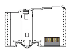
2.3 Data Contacts/Internal Bus
The communication between the I/O controller and the I/O modules, as well as the system power supply of the I/O modules are realized via the internal bus. The internal bus is made up of 6 data contacts, these gold-plated contacts are self-cleaning when connected.
2.4 Power Jumper Contacts
The power module included with the controller has two self-cleaning power jumper contacts for powering the field side. This power supply has a maximum current of 10A across the contacts, current exceeding the maximum will damage the contacts. When configuring the system, it must be ensured that the above-mentioned maximum current is not exceeded. If it exceeds, a power expansion module needs to be inserted.
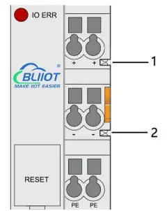
| No. | Type | Description |
| 1 | Spring contact | Supply 24V to the field side |
| 2 | Spring contact | Supply 0V to the field side |
2.5 Terminal Point
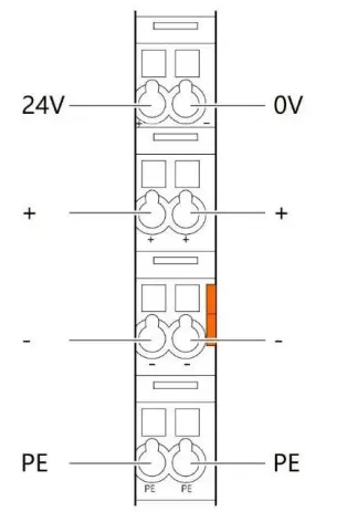
| Name | Description |
| 24V | System Power 24VDC |
| 0V | System Power 0VDC |
| + | Connections Field Supply 24 VDC |
| + | Connections Field Supply 24 VDC |
| – | Connections Field Supply 0 VDC |
| – | Connections Field Supply 0VDC |
| PE | Grounding |
| PE | Grounding |
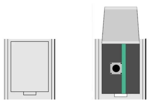
2.6 Factory Reset
This reset button is used to restore the device configuration parameters to the factory state.
Operation steps:
- When the device is running, open the flip cover;
- Press and hold the button for more than 5 seconds, until all the LED lights go off, indicates reset successful, and then the device will automatically restart.
2.7 Electrical Schematic

Installation
3.1 Installation Sequence
All distributed controllers and I/O modules from Beilai Technology must be mounted on a standard DIN 35 rail.
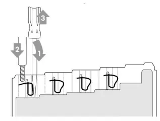
Starting from the controller, the I/O modules are assembled from left to right, and the modules are installed next to each other. All I/O modules have grooves and power jumper contacts on the right side, to avoid assembly errors, I/O modules must be inserted from the right and top to avoid damage to the modules.
Utilizes a tongue and groove system to form a secure fit and connection. With the automatic locking function, the individual components are securely fixed on the rail after installation.
Don’t forget to install the terminal module! Always plug a terminal module (eg TERM) into the end of the I/O module to ensure correct data transmission.
3.2 Install Controller
- Snap the coupler onto the DIN rail first;
- Use a tool such as a screwdriver to turn the locking cam until the locking cam engages the DIN rail.

3.3 Remove Controller
- Use a screwdriver to turn the locking disc cam until the locking cam no longer engages the rail.
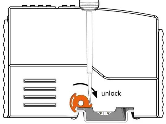
- Pull the release tab to remove the coupler from the assembly
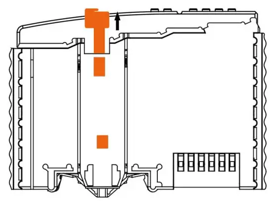
Data or power contacts are electrically disconnected from adjacent I/O modules when the controller is removed.
3.4 Insert I/O Modules
- When inserting the module, make sure the tabs on the module line up with the grooves of the controller or other I/O module to which it is attached.

- Press the I/O module into the assembly position until the I/O module snaps into the rail.
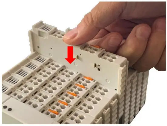
After the I/O module is installed, the electrical connection to the controller (or the previous I/O module) and the following I/O module is established via the data contacts and the power jumper contacts.
3.5 Remove I/O Modules
Pull up on the latch to remove the I/O module from the assembly.
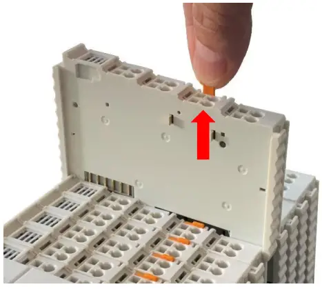
When the I/O module is removed, the electrical connection to the data or power jumper contacts is disconnection.
Device Connection
4.1 Wiring
CAGE CLAMP connection is suitable for solid, stranded and fine-stranded conductors.
Only one wire can be connected to each CAGE CLAMP. If there is more than one wire, it must be merged into a point before being connected.
- Open the CAGE CLAMP by inserting the tool into the opening above the junction.
- Insert the wire into the corresponding open connection terminal.
- Once the tool is removed, the CAGE CLAMP closes and the wire is clamped firmly by the spring.
4.2 Power Supply
System and field voltages are supplied by power supply modules. The power supply module of the BL206Pro controller supplies power for the internal electronics of the controller and the I/O modules. If necessary (there are many I/O modules and the current is relatively high), it can also be provided through an independent power supply module.
The fieldbus interface (Ethernet interface), system and field are galvanically isolated from each other.
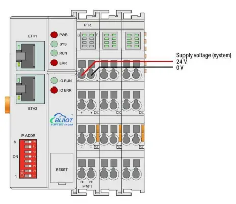
4.2.1 System Power
BL206Pro controller require 24V DC system power, which is connected from the terminal of the power supply module. The 5V bus voltage required inside the system is converted from the 24V system voltage.
The power supply module only has proper fuse protection, please provide proper overcurrent protection externally.
Please pay attention to matching the output power of the power supply module and the load power to avoid excessive load current.
 4.2.2 On-site Power Supply
The power supply module supplies 24 VDC on the field side to power the sensors and actuators.
Field power supply only has proper fuse protection. Without overcurrent protection, electronic equipment can be damaged.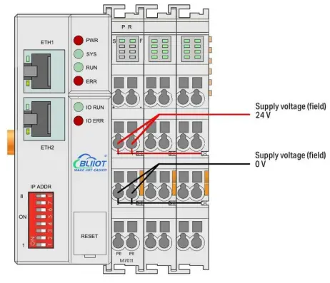
Field-side power is automatically output from the power jumper contact when the I/O module is connected. The continuous load current across the contacts of the power supply must not exceed 10 A.
The problem of excessive load power on the system side or on the field side can be solved by plugging in additional power supply modules. After plugging in an additional power supply module, a new voltage potential may appear on the field side.
In the case where electrical isolation is not required, the field power supply and the system power supply can use the same power supply.
4.2.3 Grounding
When installing the enclosure cabinet, the cabinet must be grounded, and the rail is electrically connected to the cabinet through screws to ensure that the rail is properly grounded. Grounding can increase resistance to electromagnetic interference. Some components in the I/O system have rail contacts that dissipate EMI onto the rail.

BL206 Series Controller
5.1 BL206 MQTT EdgeIO Controller
5.1.1 BL206 Overview
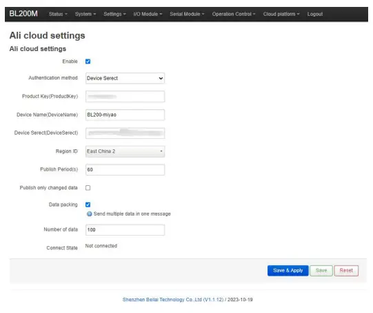
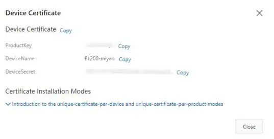
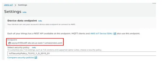
The BL206 controller supports MQTT protocol, and data can be uploaded to Alibaba Cloud, Huawei Cloud, AWS Cloud, Thingsboard, BLIIoT cloud, Custom MQTT cloud.
5.1.2 Technical Parameters
| Name | Parameters | Description |
| System power | Input voltage(system) | 24 VDC |
| Input current(system) | MAX 500 mA@24VDC | |
| Power Efficiency | 84% | |
| Internal bus voltage | 5VDC | |
| Controller current consumption | MAX 300mA@5VDC | |
| I/O current consumption | MAX 1700mA@5VDC | |
| Isolation protection | 500 V system/supply | |
| Field power | Input voltage (field) | 24 VDC |
| Current carrying capacity (power jumper contacts) | MAX 10 ADC | |
| Ethernet | Number | 2 X RJ45 |
| Transmission medium | Twisted Pair STP 100 Ω Cat 5 | |
| MAX cable length | 100m | |
| Baud rate | 10/100 Mbit/s | |
| Isolation protection | ESD contact 8KV, Surge 4KV(10/1000us) | |
|
System |
Operating system | Linux |
| CPU | 300MHz | |
| RAM | 64MB | |
| Flash | 128MB | |
| Number of I/O modules | MAX 32 | |
| Protocols | MQTT, HTTP, DHCP, DNS | |
| Wiring | Method | CAGE CLAMP |
| Wire diameter | 0.08 mm² ⋯ 2.5 mm², AWG 28 ⋯ 14 | |
| Strip length | 8 mm ⋯ 9 mm / 0.33 in | |
|
Environment |
Working temperature | 0 ⋯ 55 °C |
| Storage temperature | -40 ⋯ 70 °C | |
| Relative humidity | 5 ⋯ 95% no condensation | |
| Working altitude | 0 ⋯ 2000 m | |
| Protection | IP20 | |
| Dimension | Width | 48mm |
| Length | 100mm | |
| Height | 69mm |
| Material | Color | Light gray |
| Housing material | Polycarbonate, Nylon 6.6 | |
| Fire load | 1.239 MJ | |
| Weight | 180g | |
| Installation | Method | DIN-35 |
|
Certificated |
EMC |
EN 55022: 2006/A1: 2007 (CE &RE)
Class B |
| IEC 61000-4-2 (ESD) Level 4 | ||
| IEC 61000-4-3 (RS) Level 4 | ||
| IEC 61000-4-4 (EFT) Level 4 | ||
| IEC 61000-4-5 (Surge)Level 3 | ||
| IEC 61000-4-6 (CS)Level 4 | ||
| IEC 61000-4-8 (M/S) Level 4 |
5.1.3 Hardware Interface
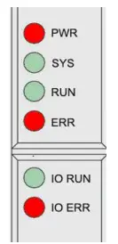
5.1.3.1 LED Indicators
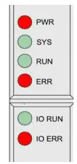
| LED | Description | Color | Status | Meaning |
| PWR | Power indicator | Red | ON | Power connection successful |
| OFF | No power | |||
| SYS | System indicator | Green | ON | System is abnormal |
| OFF | System is running normally | |||
| RUN | Running indicator | Green | Flashing | System is running normally |
| OFF | System is abnormal | |||
| ERR | Error indicator | Red | ON | Northbound protocol connection error |
| OFF | No errors |
| I/O RUN | I/O Running indicator | Green |
Flashing |
I/O module is working normally |
| OFF | Module not inserted | |||
| I/O ERR | I/O Error indicator | Red | ON | I/O module communication error |
| OFF | No errors |
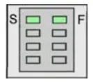
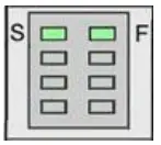
| LED | Description | Color | Status | Meaning |
|
S |
System 24V power indicator | Green | ON | Power is OK |
| OFF | No power | |||
| F | Field 24V power indicator | Green | ON | Power is OK |
| OFF | No power |
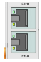
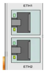
5.1.3.2 Ethernet Port
Connect to the Ethernet-based fieldbus through ETH2.
EHT1 is used to connect other nodes that need to be connected to the Ethernet.
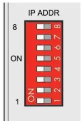
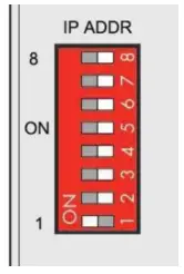
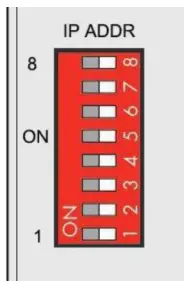
5.1.3.3 IP Address Selection Switch
The 8-bit DIP switch is used to set the IP address. The encoding of DIP switches is done bit by bit, starting from DIP switch 1 with the least significant bit (2 0) to DIP switch 8 with the most significant bit (2 7 ), corresponding to decimal values: 0-255.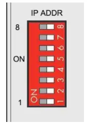
When the value of the DIP switch is 1111 1111 (decimal 255), the IP address is set according to the web page. The web page setting can specify the IP or set the automatic acquisition. When the web page is not set, the IP address is: 192.168.1.10 When the value of the DIP switch is 0000 0000 – 1111 1110 (decimal 0-254), determine the 3rd byte of the IP address, and the 1st, 2nd and 4th bytes are fixed bytes, namely 192.168.xxx.253
5.1.4 MQTT Identifiers
The MQTT identifier is REG+Modbus mapping address (such as the first DO module first DO: REG1000).
5.1.5 Controller Connection
The BL206 controller comes with 2 x RJ45 Ethernet ports, integrated switch function inside, work in store-and-forward operation mode, each port supports 10/100 Mbit transmission speed and full-duplex and half-duplex transmission mode.
The BL206 controller connect to the router Ethernet network via ETH2 only, while the EHT 1 is for connecting other nodes.
The internal integrated switch supports bypass mode, which can automatically start the bypass mode when the controller system fails, and automatically maintain the link between ETH1 and EHT2.
The wiring of these Ethernet ports conforms to the 100BaseTX specification, which specifies the use of category 5 twisted pair cable as the connecting cable. Cable types S/UTP (Screened unshielded twisted pair) and STP (shielded twisted pair) can be used up to a length of 100m.

5.1.6 Web Page Configuration
BL206 MQTT Controllerr built-in web server is a browser-based configuration utility.
When a node is connected to your network, you can access the web console by entering the IP address of the server in your web browser.
5.1.6.1 Preparation Before Configuration
To successfully access the BL206, it must be properly installed and connected to the computer. In addition, configure them with correct IP addresses to keep them in the same network segment.
5.1.6.1.1 Connect Computer and Controller
- Mount the fieldbus node on a DIN35 rail. Follow the installation instructions in the “Installation” chapter.
- Connect the 24 V power supply to the system power terminals.
- The computer and the bus node can be connected in two ways, one is that the two are connected to the switch device of the local area network through the Ethernet port; the other is that the two are directly connected point-to-point. For detailed steps, follow the instructions in the “Controller Connection” chapter.
- Turn on the power supply and start supplying power.
The controller is initialized after power-up, creates process image according to the I/O modules configuration of the node.
5.1.6.1.2 Configure Computer IP Address
There are two ways to configure PC IP address. One is to turn on the automatic IP address option on the PC’s local connection to dynamically assign DHCP in the network. The other is to configure a static IP address with the coupler node on the same network segment on the local connection of the PC.
Takes Windows 7 system as an example for configuration. Windows systems are all configured similarly.
- Click Start > Control Panel > Network and Sharing Center, and click local connection in the window that opens.

- In the local connection status window, click Properties.
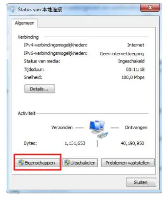
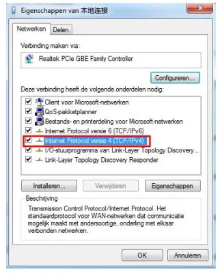
- Double-click “Internet Protocol Version 4 (TCP/IPv4)” on the local connection properties page.
- There are two ways to configure the IP address of the PC
• Obtain IP address automatically (system default mode)
To obtain an IP address automatically from a DHCP server, select “Obtain an IP address automatically”;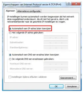 • Set a static IP address
Select “Use the following IP address” and set the correct values for the IP address, subnet mask and default gateway.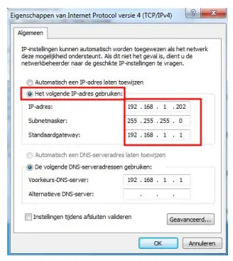
5.1.6.1.3 Configure Controller IP address
There are 2 ways to assign an IP address
- Assignment via built-in web page (static IP or automatic IP assignment)
- Assign via DIP switch (static IP)
DIP address selector switch definition
| Switch position (ON = 1) | Value | Definition |
|
0000 0000 — 1111 1110 |
0-254 |
Enable the DIP selector switch assignment function and determine the value of the 3rd byte. Example: 0010 0110 (22 decimal), the IP address is “192.168.22.253”. |
| 1111 1111 | 255 | Enable the function of specifying IP on the web page, or select the function of DHCP automatic allocation. When the IP is not allocated through the web, the IP is 192.168.1.10. |
5.1.6.1.3.1 Configuration via Web Page
The controller can be set to an IP address via the “Settings > Local Settings” page after entering the page, or it can be set to be assigned automatically. Select static address, if not set IP address, the IP is 192.168.1.10
5.1.6.1.3.2 Assign IP via DIP Switch
Set the value of the DIP address selector switch to 0000 0000 – 1111 1110 (decimal 0 254), and the IP address will be assigned by the DIP switch.
The IP address consists of fixed bytes and variable bytes. The 1st, 2nd and 4th bytes are fixed bytes, the DIP selector switch determines the 3rd byte, namely: 192.168.xxx.253
The controller assigns an IP address via a DIP switch, and the IP address set in this way is static.
5.1.6.1.4 Factory Default Settings
Before logging into the web configuration page, it is necessary for you to understand the following default parameters,
IP: Determined according to the DIP switch, if the DIP switch is 1111 1111, the default IP is 192.168.1.10
If factory default DIP switch is 0000 0000 status, then the IP is 192.168.0.253
| Item | Description |
| Username | admin |
| Password | Empty |
5.1.6.2 Login Configuration Page
- Open a browser on your computer, such as IE, Chrome, etc.
- Enter the IP address of the controller node (192.168.1.10) in the address bar of the browser to enter the user login interface.
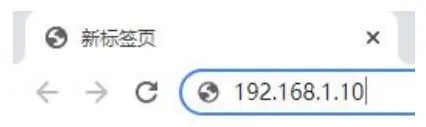
- Enter “Username” and “Password” in the login interface, and then click Login.

- After successfully logging in to the web interface, the display is as follows
30 pase


Documents / Resources
 |
BLIIOT BL206 Distributed Distributed Input Output Ethernet [pdf] User Manual BL206 Distributed Distributed Input Output Ethernet, BL206, Distributed Distributed Input Output Ethernet, Distributed Input Output Ethernet, Input Output Ethernet, Output Ethernet, Ethernet |