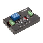
BEA BR3-X Programmable 3 Relay Logic Module

BEFORE BEGINNING INSTALLATION
READ BEFORE BEGINNING INSTALLATION & SET-UP
- Shut off all power going to header before attempting any wiring procedures.
- Maintain a clean and safe environment when working in public areas.
- Constantly be aware of pedestrian traffic around the door area.
- Always stop pedestrian traffic through the doorway when performing tests that may result in unexpected reactions by the door.
- ESD (electrostatic discharge): Circuit boards are vulnerable to damage by electrostatic discharge. Before handling any board ensure you dissipate your body’s ESD charge.
- Always check placement of all wiring before powering up to ensure that moving door parts will not catch any wires and cause damage to equipment.
- Ensure compliance with all applicable safety standards (i.e. ANSI A156.10) upon completion of installation.
- DO NOT attempt any internal repair of the components. All repairs and/or component replacements must be performed by BEA, Inc. Unauthorized disassembly or repair:
- May jeopardize personal safety and may expose one to the risk of electrical shock.
- May adversely affect the safe and reliable performance of the product resulting in a voided warranty.
SET-UP / WIRING
Set jumpers
| RELAY 1 OUTPUT | DRY/WET JUMPER2 | AC OUTPUT VOLTAGE1 | DC OUTPUT VOLTAGE2 |
| DRY | both jumpers set to DRY | N/A | N/A |
| WET1 | both jumpers set to WET | both jumpers set to AC | both jumpers set to DC |
Wiring according to desired function (reference full User’s Guide for complete set of wiring diagrams).

NOTES
- If voltage Input at the Br3-X is AC, then output selection can be AC or DC.
- When DC ‘WET’ output is selected, COM terminal is positive (+) and the ground (-) is switched between NO and NC.
PROGRAMMING

- Press and hold INCR + FUNC for 3 seconds.
- Display will toggle between FF / 00 for 5 seconds.1,2
- While FF / 00 is displayed, press INCR to cycle through functions.
- Once desired function is selected, press FUNC to cycle through parameters.
- Display will toggle between parameter and its current value for 5 seconds.
- Press 3 INCR to cycle through parameter’s values.
- Repeat steps 4-7 until all function parameters are set.
- Wait 5 seconds for Br3-X to save and display function.
- Test the device to ensure that all function parameters are working correctly and as intended for the specific application.
NOTES
- Function 00 disables the BR3-X.
- “nP” = no parameters are applicable for the selected function.
- Relay hold time(s) and delay time(s) MUST be set for any relay that is to be utilized. Ex: For function 36, if using only relay 1, h1 must be set… if using relay 1 and relay 2, h1, h2, and d1 must be set.
- Pressing and holding INCR will rapid cycle.
FUNCTIONS REFERENCE
| FUNCTION | DESCRIPTION | LOGIC |
|
10 |
timer |
• activation of relay 1 via trigger of input 1
• reverse logic available |
| 11 | ratchet / latching | • ratchet/latching of relay 1 via trigger of input 1 |
|
22 |
2-relay sequencer + inhibitor |
• sequence of relay 1 and relay 2 with inhibiting of input 1 until input 2, input 3, or WET input is triggered
• activation of input 4 reinhibits input 1 |
|
28 |
2-relay sequencer
+ door position |
• sequence of relay 1 and relay 2 via trigger of input 1 or WET input
• input 2 allows delay to run when open but not when closed |
|
29 |
deactivation timer |
• sequence of relay 1 and relay 2 via trigger of input 1 or WET input
• input 2, once opened after sequence, allows relay 1 to deactivate • input 2 allows delay to run when open but not when closed • input 3 disables sequence, reverse logic available |
|
36 |
3-relay sequencer
+ ‘1-shot’ |
• sequence of relay 1 and relay 2 and relay 3 via trigger of input 1 or WET input
• relay 1, relay 2, and relay 3 can be maintained or ‘1-shot’ |
|
37 |
3-relay sequence with
‘independent relay’ |
• sequence of relay 1 and relay 2 and relay 3 via trigger of input 1 or WET input
• relay 1, relay 2, and relay 3 can be ‘independent’ or sequenced |
| 50 | interlock timer | • interlock of relay 1 and relay 2 via trigger of input 1 and input 2, respectively |
|
55 |
interlock ratchet / latching | • interlock ratchet of relay 1 and relay 2 via trigger of input 1 and input 2, respec- tively |
|
65 |
2-way 2-relay sequence |
• sequence of relay 1 and relay 2 via trigger of input 1
• sequence of relay 2 and relay 1 via trigger of input 2 • input 3 triggers relay 1 individually, input 4 triggers relay 2 individually |
|
NL |
normally locked restroom | • sequence of relay 1 (lock), relay 2 (door), and relay 3 (occupied indicators) for normally locked, single occupancy restrooms |
|
NU |
normally unlocked restroom | • sequence of relay 1 (lock), relay 2 (door), and relay 3 (occupied indicators) for normally unlocked, single occupancy restrooms |
|
DN |
3-relay sequencer + ‘day / night mode’ | • sequence of relay 1 and relay 2 and relay 3 via trigger of input 1 or WET input
• input 2 operation dependent upon input 4 (‘day / night mode’) |
|
00 |
disable |
• Br3-X disabled
• 00 is the default setting and has no assigned function |
PARAMETERS REFERENCE
| PARAMETER | DESCRIPTION | LOGIC | |
|
h1* |
relay 1 hold time |
00 – 60 seconds
countdown begins AFTER release of input 1 or WET input |
|
|
h2* |
relay 2 hold time |
00 – 60 seconds
countdown begins AFTER d1 (delay between relay 1 & relay 2) expires |
|
|
h3* |
relay 3 hold time |
00 – 60 seconds
countdown begins AFTER d2 (delay between relay 1 & relay 3) expires |
|
|
d1 |
delay between relay 1 & relay 2 | 00 – 60, _1 (1/4), _2 (1/2), _3 (3/4) seconds delay begins AT activation of input 1 or WET input | |
|
d2 |
delay between relay 1 & relay 3 | 00 – 60, _1 (1/4), _2 (1/2), _3 (3/4) seconds delay begins AT activation of input 1 or WET input | |
|
rL |
reverse logic |
00 = normal logic
input 1 trigger must be NO and close its contact to trigger |
01 = reverse logic
input 1 trigger must be NC and open its contact to trigger |
| nP | no parameters | no parameters available for selected function | |
TECHNICAL SPECIFICATIONS
| Supply Voltage | 12 − 24 VAC/VDC ±10% |
| Current Consumption | 30 − 130 mA (DRY output) |
| Input
Input 1, 2, 3, 4 WET input |
DRY contact 5-24 VAC/VDC ±10% |
| Contact Rating Relay 1 (DRY)
Relay 1 (WET) Relay 2 Relay 3 |
3 A @ 24 VAC or 30 VDC 1 A 3 A @ 24 VAC or 30 VDC 1 A @ 24 VAC or 30 VDC |
Specifications are subject to change without prior notice.
All values measured in specific conditions.
COMPLIANCE EXPECTATIONS
BEA, INC. INSTALLATION/SERVICE COMPLIANCE EXPECTATIONS
BEA, Inc., the sensor manufacturer, cannot be held responsible for incorrect installations or incorrect adjustments of the sensor/device; therefore, BEA, Inc. does not guarantee any use of the sensor/device outside of its intended purpose. BEA, Inc. strongly recommends that installation and service technicians be AAADM-certifi ed for pedestrian doors, IDA-certifi ed for doors/ gates, and factory-trained for the type of door/gate system. Installers and service personnel are responsible for executing a risk assessment following each installation/service performed, ensuring that the sensor/device system performance is compliant with local, national, and international regulations, codes, and standards. Once installation or service work is complete, a safety inspection of the door/gate shall be performed per the door/gate manufacturer’s recommendations and/or per AAADM/ANSI/DASMA guidelines (where applicable) for best industry practices.
Safety inspections must be performed during each service call – examples of these safety inspections can be found on an AAADM safety information label (e.g. ANSI/DASMA 102, ANSI/DASMA 107, UL294, UL325, and International Building Code). Verify that all appropriate industry signage, warning labels, and placards are in place.

Contact
- Tech Support & Customer Service: 1-800-523-2462
- General Tech Questions: techservices-us@BEAsensors.com
- Tech Docs: www.BEAsensors.com
Visit website for full User’s Guide and language options

Documents / Resources
 |
BEA BR3-X Programmable 3 Relay Logic Module [pdf] User Guide BR3-X Programmable 3 Relay Logic Module, BR3-X, Programmable 3 Relay Logic Module, 3 Relay Logic Module, Logic Module, Module |
 |
BEA BR3-X Programmable 3-Relay Logic Module [pdf] Owner's Manual BR3-X Programmable 3-Relay Logic Module, BR3-X, Programmable 3-Relay Logic Module, 3-Relay Logic Module, Logic Module |