BA-RCV-BLE-EZ-BAPI Wireless Receiver and Analog Output Modules

Product Information
Specifications
- Product: Wireless Receiver and Analog Output Modules
- Model Number: 50335_Wireless_BLE_Receiver_AOM
- Compatibility: Works with up to 32 sensors and 127 different modules
Overview
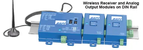
The Wireless Receiver from BAPI receives signals from wireless sensors and transmits data to Analog Output Modules via an RS485 four-wire bus. The modules convert the signal to analog resistance, voltage, or relay contact for the controller.
Setpoint Output Module (SOM)
The SOM converts setpoint data from a wireless room sensor into resistance or voltage. It offers five factory-set voltage and resistive ranges with optional override functions.
Relay Output Module (RYOM)
The RYOM converts data from the wireless receiver into a solid-state switch closure for the DDC controller. It can be configured as a momentary or latching output relay.
Product Usage Instructions
Pairing of Sensor, Receiver, and Output Modules
Pairing a Sensor to the Receiver
- Select the sensor to pair and apply power to it.
- Apply power to the receiver. The blue LED will light up.
- Press and hold the Service Button on the receiver until the blue LED starts flashing. Then press the Service Button .
FAQs
How many sensors can the receiver accommodate?
The receiver can accommodate up to 32 sensors.
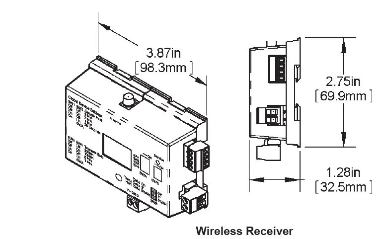
Wireless Receiver and Analog Output Modules
Installation and Operating Instructions
Overview and Identification
The Wireless Receiver from BAPI receives the signal from one or more wireless sensors and supplies the data to Analog Output Modules through an RS485 four-wire bus. The modules convert the signal to an analog resistance, voltage or relay contact for the controller. The receiver can accommodate up to 32 sensors and 127 different modules.
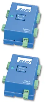
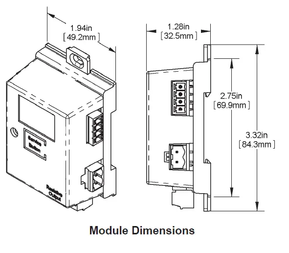
RESISTANCE OUTPUT MODULE (ROM)
Converts the temperature data from the receiver into a 10K-2, 10K-3, 10K-3(11K) or 20K thermistor curve. The 10K-2 unit has an output range of 35 to 120ºF (1 to 50ºC). The 10K-3 unit has an output range of 32 to 120ºF (0 to 50ºC). The 10K-3(11K) unit has an output range of 32 to 120ºF (0 to 50ºC). The 20K unit has an output range of 53 to 120ºF (12 to 50ºC). The specific output range is shown on the product label.
VOLTAGE OUTPUT MODULE (VOM)
Converts the temperature or humidity data from the receiver into a linear 0 to 5 or 0 to 10 VDC signal. The module has eight factory set temperature range, and the specific range is shown on the product label. The ranges are: 50 to 90ºF (10 to 32°C), 55 to 85°F (13
to 30°C), 60 to 80°F (15 to 27°C), 65 to 80°F (18 to 27°C), 45 to 96°F (7 to 35°C), -20 to 120°F (-29 to 49°C), 32 to 185°F (0 to 85°C) and -40 to 140°F (-40 to 60°C).
The module has two humidity ranges of 0 to 100% or 35 to 70%RH and the specific range is shown on the label.
THE SETPOINT OUTPUT MODULE (SOM)
Converts the setpoint data from a wireless room sensor into a resistance or a voltage. There are five factory set voltage and resistive ranges, each with an optional override function. The voltage ranges are 0 to 5V, 3.7 to 0.85V, 4.2 to 1.2V, 0 to 10V and 2 to 10V. The resistive range are 0 to 10KΩ, 0 to 20KΩ, 4.75K to 24.75KΩ, 6.19K to 26.19KΩ, 7.87K to 27.87KΩ. The specific range is shown on the product label.
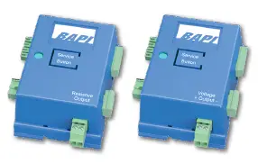 RELAY OUTPUT MODULE (RYOM)
Converts the data from the wireless receiver into a solid state switch closure for the DDC controller. The RYOM is a customer-configured momentary or latching output relay. It can be trained to various BLE wireless sensors such as the override on the BAPI-Stat “Quantum” room sensor, the magnetic door switch on the BAPI-Stat “Quantum Slim” or the output of the water leak detector. 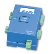
Pairing of the Sensor, Receiver and Analog Output Modules
The installation process requires that each wireless sensor is paired to its associated receiver and then to its associated output module or modules. The pairing process is easiest on a test bench with the sensor, receiver and output modules within arm’s reach of each other. Be sure to place a unique identification mark on the sensor and its associated output module or modules after they have been paired to each other so that they can be identified at the job site. If more than one variable is transmitted by the sensor (temperature, humidity and setpoint for instance), each variable requires a separate output module. Multiple output modules can be paired to the same variable if desired. 
PAIRING A SENSOR TO THE RECEIVER
You must pair the sensor to the receiver before pairing the sensor to an analog output module.
- Select the sensor that you wish to pair to the receiver. Apply power to the sensor. See its manual for detailed instructions.
- Apply power to the receiver. The blue LED on the receiver will light and remain lit.
- Press and hold the “Service Button” on the top of the receiver until the blue LED starts to flash, Fig. 1: Receiver and Output Modules Service Buttons then press and release the “Service Button” on the sensor (Figs 2 & 3) that you want to pair to the receiver. When the LED on the receiver returns to a solid “On” and the green “Service LED” on the sensor circuit board blinks rapidly three times, the pairing is complete. Repeat this process for all sensors.
PAIRING AN OUTPUT MODULE TO A SENSOR
Once the sensor is paired to the receiver, you can pair output modules to the sensor’s variable.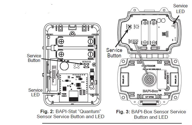
- Select the output module for the desired sensor variable and range and connect it to the wireless receiver (Fig 1).
- Press and hold the “Service Button” on the top of the output module until the blue LED begins to flash (about 3 seconds). Then, send a “pairing transmission signal” to that output module by pressing and releasing the “Service Button” on the wireless sensor. The blue LED on the receiver will flash once indicating that a transmission was received; then the blue LED on the output module will go solid for about 2 sensor and output module are now paired to each other and will remain paired to one another through battery replacement or if power is removed from wire power units. The output module’s blue LED will now flash once whenever it receives a transmission from the sensor.
Note: The wireless sensors are often measuring and transmitting multiple varibles, such as temperature and humidity, or temperature, humidity and setpoint. All of these variables are transmitted when the sensor’s “Service Button” is pressed. However, each Analog Output Module is configured at the time of order to a specific variable and range so it will only pair to that variable and not the others.
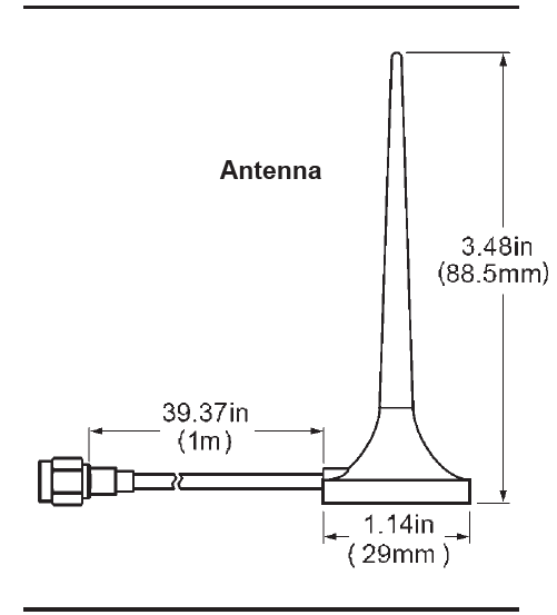
Mounting and Locating of Antenna
The antenna has a magnetic base for mounting. Although the receiver may be located inside a metal enclosure, the antenna must be outside the enclosure. There must be a non-metallic line of sight from all the sensors to the antenna. Acceptable line of sight includes walls made from wood, sheet rock or plaster with non-metallic lath. The orientation of the antenna (horizontal or vertical) will also affect the performance and varies by application.
Mounting the antenna on a metal surface will cut off reception from behind the surface. Frosted windows may block reception too. A wooden or plastic furring strip attached to a ceiling beam makes a great mount. The antenna may be hung from any ceiling fixture using fiber or plastic twine. Do not use wire to hang, and do not use perforated metal strapping, commonly called plumbers tape.
Mounting of Receiver and Analog Output Modules
The receiver and output modules can be snaptrack, DIN Rail or surface mounted. Each receiver can accommodate up to 127 modules. Start with the receiver at the far left, then securely attach each output module to the right.
Push in the blue mounting tabs to mount in 2.75” snaptrack (Fig 4). Push out the mounting tabs for DIN Rail (Fig 5). Catch the EZ mount hook on the edge of the DIN rail (Fig 6) and rotate into place. Push out the mounting tabs for surface mounting using the four supplied screws, one in each tab (Fig 7).
If your output modules cannot fit in one straight line because of limited space, then mount a second string of modules above or below. Connect wires from the right side of the first string of modules to the left side of the second string of modules.
This configuration requires one or more Pluggable Terminal Block Connector Kits (BA/AOM-CONN) for the extra wire terminations on the left and right side of the Analog Output Modules.
Each kit includes one set of 4 connectors.


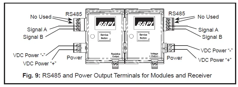
Termination
The Wireless Receiver and Analog Output Modules are pluggable and can be connected in an attached string as shown at right. The power for the analog output modules is supplied by the receiver in this configuration. If the modules are powered separately rather than from the receiver (as shown below), then they must have 15 to 40 VDC only. Be sure that you supply enough power for all the devices on the bus.

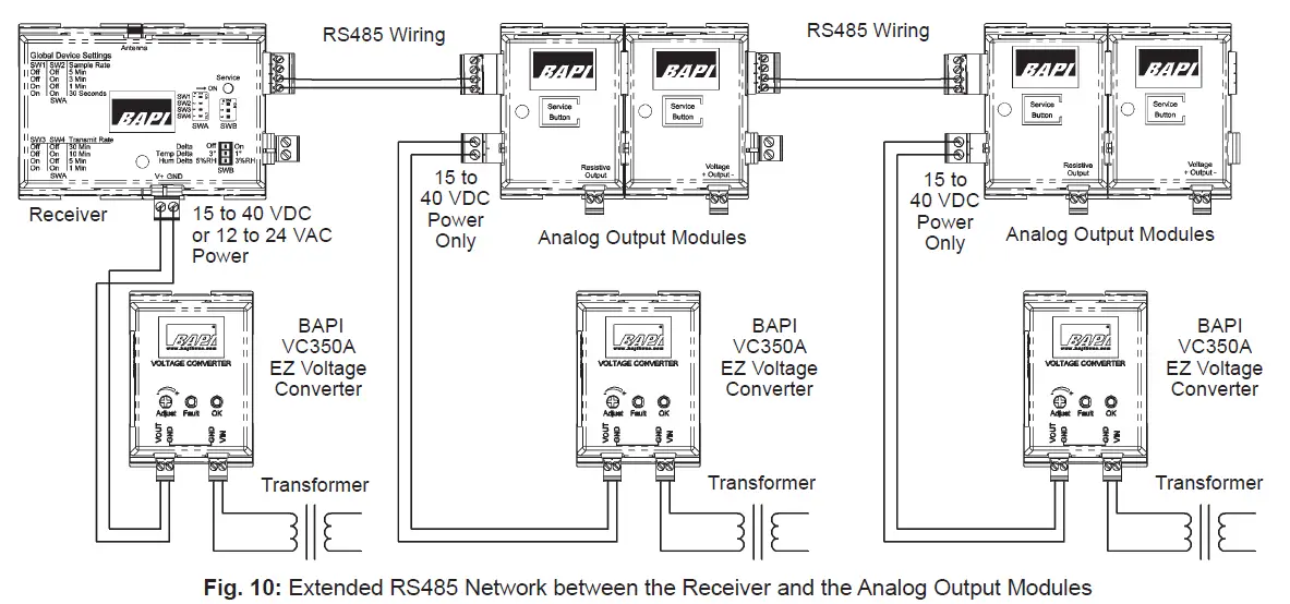
Extending the RS485 Network between the Receiver and the Analog Output Modules
The Analog Output Modules may be mounted up to 4,000 feet away from the receiver. The total length of all the shielded, twisted pair cables shown in Fig. 10
is 4,000 feet (1,220 meters). Connect the terminals together as shown in Fig. 10. If the distance from the receiver to the group of Analog Output Modules is greater than 100 feet (30 meters), provide a separate power supply or voltage converter (such as BAPI’s VC350A EZ) for that group of Analog Output Modules. Note: The configuration in Fig 10 requires one or more Pluggable Terminal Block Kits as shown on the previous page.
Receiver Switch Settings
All sensor settings are controlled and adjusted by the receiver to suit the needs of the installation. These are adjusted via the DIP switches on the top of the receiver. These are the settings for ALL OF THE SENSORS that are paired to that receiver.
Sample Rate/Interval – The time between when the sensor wakes up and takes a reading. The available values 30 sec, 1 min, 3 min or 5 min.
Transmit Rate/Interval – The time between when the sensor transmits the readings to the receiver. The available values are 1, 5, 10 or 30 minutes.
Delta Temperature – The change in temperature between a sample and the last transmission that will cause the sensor to override the transmit interval and immediately transmit the changed temperature. The available values are 1 or 3 °F or °C.
Delta Humidity – The change in humidity between a sample and the last transmission that will cause the sensor to override the transmit interval and immediately transmit the changed humidity. The available values are 3 or 5 %RH.
Resetting a Sensor, Receiver or Analog Output Module
Sensors, receivers and output modules remain paired to each other when power is interrupted or the batteries are removed. To break the bonds between them, the units need to be reset as described below:
- TO RESET A SENSOR:
Press and hold the “Service Button” on the sensor for about 30 seconds. During those 30 seconds, the green LED will be off for about 5 seconds, then flash slowly, then begin flashing rapidly. When the rapid flashing stops, the reset is complete. The sensor can now be paired to a new receiver. To re-pair to the same receiver, you must reset the receiver. Output modules that were previously paired to the sensor do not need to be re-paired. - TO RESET AN OUTPUT MODULE:
Press and hold the “Service Button” on the top of the unit for about 30 seconds. During those 30 seconds, the blue LED will be off for the first 3 seconds and then flash for the remaining time. When the flashing stops, release the “Service Button” and the reset is complete. The unit can now be re-paired to a sensor variable. - TO RESET A RECEIVER:
Press and hold the “Service Button” on the sensor for about 20 seconds. During those 20 seconds, the blue LED will flash slowly, then begin flashing rapidly. When the rapid flashing stops and returns to solid blue, the reset is complete. The unit can now be re-paired to wireless sensors. Caution! Resetting the receiver will break the bonds between the receiver and all sensors. You will have to reset each sensor and then re-pair each of the sensors to the receiver.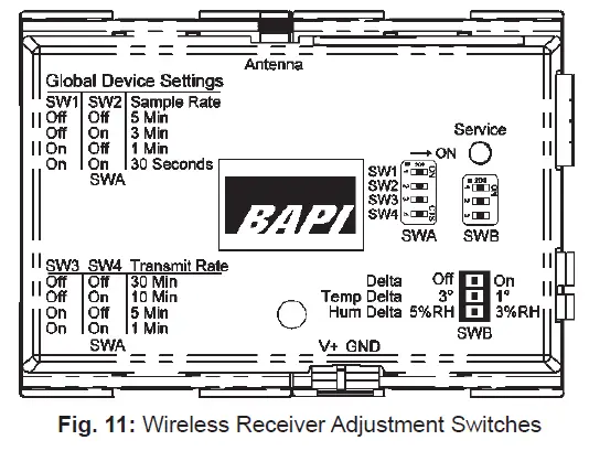

Default Status When Wireless Transmission is Interrupted
If an output module does not receive data from its assigned sensor for 35 minutes, the blue LED on the top of the module will blink rapidly. If this happens, the individual Analog Output Modules will react as follows:
- Resistance Output Modules (BA/ROM) will output the highest resistance in their output range.
- Voltage Output Modules (BA/VOM) calibrated for temperature will set their output to 0 volts.
- Voltage Output Modules (BA/VOM) calibrated for humidity will set their output to their highest voltage (5 or 10 volts).
- Setpoint Output Modules (BA/SOM) will hold their last value indefinitely.
When a transmission is received, the output modules will revert to normal operation in 60 seconds or less.
Receiver Specifications
- Supply Power: 15 to 40 VDC or 12 to 24 VAC (from halfwave rectified supply)
- Power Consumption: 30mA @ 24 VDC, 2.75 VA @ 24 VAC
- Capacity/Unit: Up to 32 sensors and 127 different Analog Output Modules
- Reception Distance:
Varies by application*
- Frequency: 2.4 GHz (Bluetooth Low Energy)
Bus Cable Distance:
- 4,000 ft with shielded, twisted pair cable
Environmental Operation Range:
- Temp: 32 to 140°F (0 to 60°C)
- Humidity: 5 to 95% RH non-condensing
- Enclosure Material & Rating: ABS Plastic, UL94 V-0
- Agency: RoHS / FCC: T4FSM221104 / IC: 9067A-SM221104
This device complies with Part 15 of the FCC Rules. Operation is subject to the following two conditions:
- This device may not cause harmful interference, and
- This device must accept any interference received, including interference that may cause undesirable operation.
Any changes or modifications not expressly approved by [company] could void the user’s authority to operate the equipment.
This device complies with Industry Canada (IC) license-exempt RSS standard(s). Operation is subject to the following two conditions. This device may not cause interference.
This device must accept any interference, including interference that may cause undesired operation of the device.
Analog Output Module Specifications
ALL MODULES
- Supply Power (VDC Only): 15 to 40 VDC (from halfwave rectified supply)
Environmental Operation Range:
- Temp: 32°F to 140°F (0°C to 60°C)
- Humidity: 5% to 95% RH non-condensing
Bus Cable Distance:
- 4,000 ft (1,220m) w/ shielded, twisted pair cable
- Enclosure Material & Rating: ABS Plastic, UL94 V-0
- Agency: RoHS
SETPOINT OUTPUT MODULE (SOM)
Power Consumption:
- Resistance Models: 20 mA @ 24 VDC
- Voltage Models: 25 mA @ 24 VDC
- Output Current: 2.5 mA @ 4KΩ load
Lost Communication Timeout:
- 35 min. (Fast Flash) : Reverts to its last command
- Analog Input Bias Voltage:
- 10 VDC max (Resistance Output Models only)
Output Resolution:
- Resistance Output: 100Ω
- Voltage Output: 150µV
- VOLTAGE OUTPUT MODULE (VOM)
Power Consumption: 25 mA @ 24 VDC
Output Current: 2.5 mA @ 4KΩ load - Lost Communication Timeout:
35 min. (Fast Flash)
Temperature output reverts to 0 volts
%RH output reverts to high scale (5V or 10V) - Output Voltage Range:
0 to 5 or 0 to 10 VDC (factory calibrated)
Output Resolution: 150µV - RESISTANCE OUTPUT MODULE (ROM)
- Power Consumption:
20 mA @ 24 VDC
Analog Input Bias Voltage: 10 VDC max - Lost Communication Timeout:
35 min. (Fast Flash)
Reverts to High Resistance >35KΩ (Low Temp)
Temperature Output Ranges:
10K-2 Unit: 35 to 120ºF (1 to 50ºC)
10K-3 Unit: 32 to 120ºF (0 to 50ºC)
10K-3(11K) Unit: 32 to 120ºF (0 to 50ºC) 20K Unit: 53 to 120ºF (12 to 50ºC)
Output Resolution: 100Ω - RELAY OUTPUT MODULE (RYOM)
- Power Consumption:
20 mA @ 24 VDC
Analog Input Bias Voltage:
10 VDC max - Lost Communication Timeout:
35 minutes (Fast Flash)
Reverts to last command
Relay Output:
40V (DC or AC peak), 150 mA max.
Off state leakage current 1 uA max.
On state resistance 15Ω max. - Operation:
Momentary: 5 second momentary actuation Latching: Latching actuation
Building Automation Products, Inc., 750 North Royal Avenue, Gays Mills, WI 54631 USA
Tel:+1-608-735-4800 • Fax+1-608-735-4804 • E-mail: sales@bapihvac.com • Web : www.bapihvac.com
Documents / Resources
 |
BAPI BA-RCV-BLE-EZ-BAPI Wireless Receiver and Analog Output Modules [pdf] Installation Guide BA-RCV-BLE-EZ-BAPI, 50335_Wireless_BLE_Receiver_AOM, BA-RCV-BLE-EZ-BAPI Wireless Receiver and Analog Output Modules, BA-RCV-BLE-EZ-BAPI, Wireless Receiver and Analog Output Modules, Receiver and Analog Output Modules, Analog Output Modules, Output Modules, Modules |


