![]() 52432_ins_BBX_Humidity_Duct
52432_ins_BBX_Humidity_Duct
Duct Humidity Sensor with BAPI-Box Crossover
Enclosure and Optional Temperature Sensor
Installation & Operations
Overview and Identification
The Duct Humidity Sensors in the BAPI-Box Crossover enclosure come in 2%RH and 3%RH accuracies with a 0 to 5, 1 to 5, 0 to 10 or 2 to 10VDC output or a loop powered 4 to 20mA output. They are available with an optional RTD or thermistor temperature sensor. The BAPI-Box Crossover enclosure has a hinged cover for easy termination and carries an IP44 rating with a knockout plug in the open port. It includes a green power indication LED visible through the cover. This instruction sheet is specific to units with the BAPI-Box Crossover Enclosure. For other enclosures, please refer to the BAPI website or contact you BAPI representative.

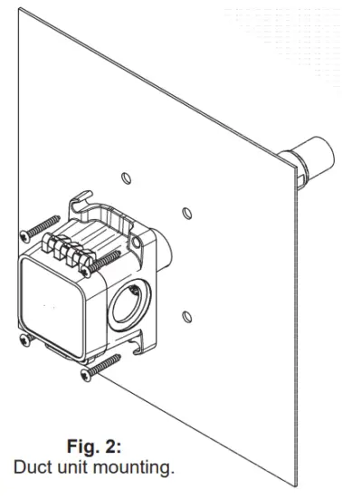
Mounting
Mount at least three duct diameters from humidifiers in the center of the duct wall. Drill a 1 inch hole for the probe in the duct and use two number 8 sheet metal screws to attach the sensor to the duct. Center the probe in its mounting hole. Be sure that the foam seals the hole, but do not over tighten the screws.
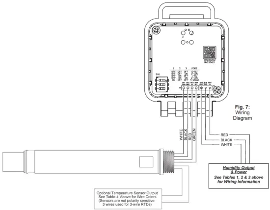
Wiring and Termination
BAPI recommends using twisted pair of at least 22AWG and sealant filled connectors for all wire connections. Larger gauge wire may be required for long runs. All wiring must comply with the National Electric Code (NEC) and local codes. Do not run this device’s wiring in the same conduit as AC power wiring of NEC class 1, NEC class 2, NEC class 3 or with wiring used to supply highly inductive loads such as motors, contactors and relays. BAPI’s tests show that fluctuating and inaccurate signal levels are possible when AC power wiring is present in the same conduit as the signal lines. If you are experiencing any of these difficulties, please contact your BAPI representative.
![]() BAPI recommends wiring the product with power disconnected. Proper supply voltage, polarity, and wiring connections are important to a successful installation. Not observing these recommendations may damage the product and will void the warranty.
BAPI recommends wiring the product with power disconnected. Proper supply voltage, polarity, and wiring connections are important to a successful installation. Not observing these recommendations may damage the product and will void the warranty.
| Table 1: Humidity Transmitter with 4 to 20mA Output | ||
| Wire Color | Purpose | Note |
| White | Not Used | Not Used |
| Black | Humidity Output | 4 to 20mA, To Analog Input of Controller |
| Red | Power | 7 to 40VDC |
| Table 3: Humidity Transmitter with 0 to 10 or 2 to 10VDC Output | ||
| Wire Color | Purpose | Note |
| White | Humidity Output | 0 to 10 or 2 to 10VDC, To Analog Input of Controller |
| Black | GND (Common) | Ground for Power and Humidity Output |
| Red | Power | 13 to 40VDC or 18 to 32VAC |
| Table 4: Temperature Sensor Lead Wire Colors | |||
| Thermistors | Platinum RTDs – 2 Wire | ||
| 1.8KΩ | Orange/Red | 100Ω | Red/Red |
| 2.2KΩ | Brown/White | 1KΩ | Orange/Orange |
| 3KΩ | Yellow/Black | Nickel RTD | |
| 3.25KΩ | Brown/Green | 1KΩ | Green/Green |
| 3.3KΩ | Yellow/Brown | Silicon RTD | |
| 10K-2Ω | Yellow/Yellow | 2KΩ | Brown/Blue |
| 10K-3Ω | Yellow/Red | Platinum RTDs – 3 Wire | |
| 10K-3(11K)Ω | Yellow/Blue | 100Ω | Red/Red/Black* |
| 20KΩ | White/White | 1KΩ | Orange/Orange/Black* |
| 47KΩ | Yellow/Orange | *In the 3-Wire RTD sensors listed above, the two wires of similar color are connected together. | |
| 50KΩ | White/Blue | ||
| 100KΩ | Yellow/White | ||
Additional sensors are available so your sensor may not be listed on this table.
NOTE: BAPI’s ±2% and ±3% humidity transmitters ARE polarity sensitive as well as reverse polarity protected.
| Table 2: Humidity Transmitter with 0 to 5 or 1 to 5VDC Output | ||
| Wire Color | Purpose | Note |
| White | Humidity Output | 0 to 5 or 1 to 5VDC, To Analog Input of Controller |
| Black | GND (Common) | Ground for Power and Humidity Output |
| Red | Power | 7 to 40VDC or 18 to 32VAC |
Filter Care
A sintered filter protects the humidity sensor from various airborne particles and may need periodic cleaning. To do this, gently unscrew the filter from the probe. Rinse the filter in warm soapy water and rinse until clean. A nylon brush may be used if necessary. Gently replace the filter by screwing it back into the probe. The filter should screw all the way into the probe. Hand tighten only. If a replacement filter is needed, call BAPI.
BA/HDOFS3: Stainless Steel Sintered Filter Replacement for Outside Air Units
Humidity Diagnostics
| Possible Problems: | Possible Solutions: | ||||||||||||
| Unit will not operate | Check for proper supply power. (See page 2 for wiring diagram and power specifications) | ||||||||||||
| Humidity output is at its maximum | Make sure the humidity sensor is wired properly. Verify humidity with a reference sensor. If humidity drops to 5% or below in the environment, the output will go to the maximum value.D375 |
||||||||||||
| Humidity output is at its minimum | Make sure the humidity sensor is wired properly. | ||||||||||||
| Humidity reading in controller’s software appears to be off by more than the specified accuracy | Check all software parameters Determine if the sensor is exposed to an external air source different from the intended measured environment or reference device.D376 |
||||||||||||
|
Check the Humidity transmitter output against a calibrated reference such as a 2% accurate hygrometer. Measure the humidity at the sensor’s location using the reference meter, then calculate the humidity transmitter output using the humidity formula at left. Compare the calculated output to the actual humidity transmitter output (see the wiring diagram on page 2 for the humidity transmitter output wire colors). If the calculated output differs from the humidity transmitter output by more than 5%, contact BAPI technical support. |
Temperature Diagnostics
| Possible Problems: | Possible Solutions: |
| Controller reports Incorrect temperature |
Confirm the input is set up correctly in the controller’s software – Verify that the sensor wires are not physically shorted or open – Check wiring for proper termination – Measure the temperature at the temperature sensor’s location using an accurate temperature standard. Disconnect the temperature sensor wires and measure the temperature sensor’s resistance with an ohmmeter. Compare the temperature sensor’s resistance to the appropriate temperature sensor table on the BAPI website. If the measured resistance is different from the temperature table by more than 5%, call BAPI technical support. BAPI’s web site is found at www.bapihvac.com; click on “Resource Library” and “Sensor Specs” then click on the type of sensor you have. |
Humidity Output DIP Switch Note:
The transmitter circuit board may have a three position DIP switch that controls the humidity output value. This switch is set at the factory at the time of the order. The settings of the switch are shown at right in case you want to change them in the field. Be aware that the power requirements for the unit change depending on the humidity output value. See the specifications section for power requirements.

The black square represents the switch position, i.e., the “0-5Vout” has all switches in the “off” position
Specifications
Power:
10 to 35VDC ………………… For 0 to 5 or 1 to 5VDC or 4 to 20 mA Humidity Outputs
15 to 35VDC …………………. For 0 to 10 or 2 to 10VDC Humidity Output
12 to 27VAC …………………. For 0 to 5 or 1 to 5VDC Humidity Output
15 to 27VAC …………………. For 0 to 10 or 2 to 10VDC Humidity Output
Power Consumption:
22 mA max. DC ……………. For 0 to 5 or 1 to 5VDC or 4 to 20 mA Humidity Outputs
6 mA max. DC ……………… For 0 to 10 or 2 to 10VDC Humidity Outputs
0.53 VA max. AC …………… For 0 to 5 or 1 to 5VDC Humidity Output
0.14 VA max. AC …………… For 0 to 10 or 2 to 10VDC Humidity Output
Sensor:
Humidity……………………….. Capacitive Polymer
Drift ……………………………. 0.5% per year
Response time………………. < 5 seconds in moving air
RH Linearity ………………….. Negligible, factory corrected linear from 10 to 80% RH
RH Hysteresis ……………… Factory corrected to <1%
Opt. Temp. ……………………. Passive RTD or Thermistor
System Accuracy:
2% RH …………………………. ±2% (10 to 80% RH @ 25°C), ±3% (80 to 90% RH @ 25°C), Non-condensing
3% RH …………………………. ±3% (10 to 90% RH @ 25°C), Non-condensing
Thermistor ……………………. ±0.36ºF (0.2ºC) from 32 to 158ºF (0 to 70ºC) – High accuracy units are available
RTD ……………………………. ±0.55ºF (0.31ºC) @ 32ºF (0ºC) – High accuracy units are available
Filter: ……………………………. 80 micron sintered stainless steel filter
Output: Selectable via wiring detail
Humidity……………………….. 0 to 5, 1 to 5, 0 to 10 or 2 to 10VDC or 4 to 20mA at 0 to 100% RH
Opt. Temp. ……………………. Resistance RTD or Thermistor
Humidity Output Impedance:
Current ………………………… 700Ω@ 24VDC, Voltage drop is 10VDC
(Supply Voltage DC – Transmitter voltage drop 10VDC) / 0.02 Amps = Max load Impedance
Voltage…………………………. 10KΩ
Probe Length: ………………… 5.3” (13.5cm) Duct Insertion, 1” diameter
Termination: Open wire
Crimp: 18 to 26 AWG with Sealant Filled
Crimp Connector (BA/SFC1000)
Wire Nut: 26 to 16 AWG with Sealant Filled
Wire Nut (BA/SFC2000)
Enclosure Material & Rating:
UV-resistant Polycarb., IP10, NEMA 1
(IP44 with knockout plug in open port)
Environmental Operation Range:
-40 to 158ºF (-40 to 70ºC) 0% to 100% RH
Agency:
CE EN 61326-1:2013 EMC
(Industrial Electromagnetic Environment), RoHS

Specifications subject to change without notice.
Building Automation Products, Inc., 750 North Royal Avenue, Gays Mills, WI 54631 USA
Tel:+1-608-735-4800
Fax+1-608-735-4804
E-mail:sales@bapihvac.com
Web:www.bapihvac.com
Documents / Resources
 |
BAPI 52432 Duct Humidity Sensor with Crossover Enclosure [pdf] Installation Guide 52432, 52432 Duct Humidity Sensor with Crossover Enclosure, Duct Humidity Sensor with Crossover Enclosure, Humidity Sensor with Crossover Enclosure, Sensor with Crossover Enclosure, Crossover Enclosure, Enclosure |