FAQ
- Q: Can non-Modbus devices be integrated into a Modbus system using this product?
- A: Yes, the product allows for integration of non-Modbus devices into a Modbus system. Refer to the manual for more information on this feature.
Features
- Compact Modbus® device converter with the ability to send 4 ports of discrete input and 4 ports of analog input data (voltage or current)
- This Modbus converter can also output discrete values and analog outputs (voltage or current) through any of the respective sets of 4 ports
- 2-Channel Discrete Features:
- Enabled Delay Modes: ON/OFF Delay, ON/OFF One-shot, ON/ OFF Retriggerable One-shot, ON/OFF Pulse-stretcher and Totalizer
- Measurement Metrics: Count, Counts Per Minute (CPM), and Duration
- Discrete input/output can be independently configured as NPN or PNP
- Discrete Mirroring: Discrete signals (In/Out) from the four discrete ports can be mirrored to any of the output channels of the four discrete ports
- Analog In/Out Features:
- Analog Out Mirroring: The analog input from all four analog ports can be mirrored as an output to any of the four analog ports
- PFM Output: The analog input from all four analog ports can be mirrored as PFM outputs to any of the four discrete ports.
- Rugged overmolded design meets IP65, IP67, and IP68
- Connects directly to a sensor or anywhere in-line for ease of use
- R95C Modbus hubs are a quick, easy, and economical way to integrate non-Modbus devices into a Modbus system
Models
| Model Number | Function | Converter Type | Control | Connectors |
|
R95C-4B4UI-MQ |
Converter |
8-ports:
4B: 4 ports, bimodal discrete input/output 4UI: 4 ports, analog input/output |
Modbus® |
(8) Integral 4-pin M12 female quick-disconnect connectors
(1) Integral 5-pin M12 male quick-disconnect connector |
Overview
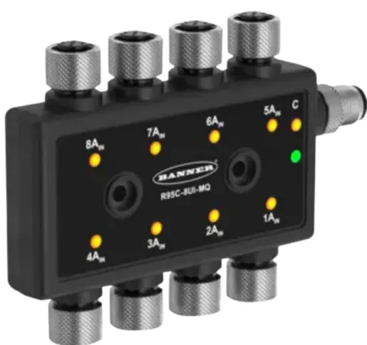
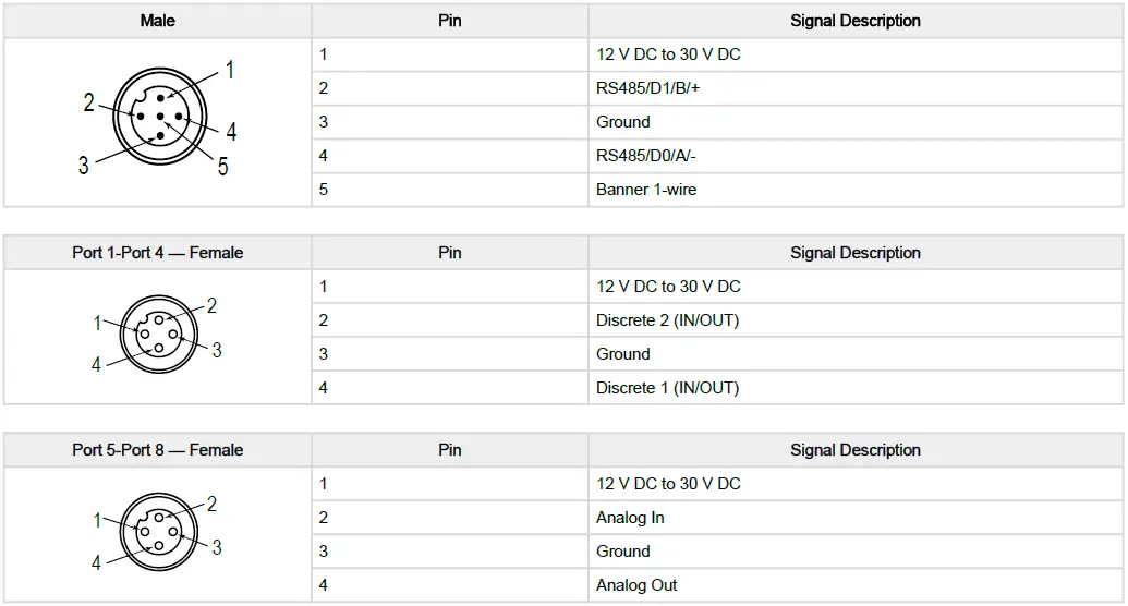
The R95C 8-Port 2-Channel Discrete and Analog In/Out Modbus® Hub provides a mix of both discrete input/output and analog input/output functionality distributed to two sets of 4-ports Ports 1 through 4 contain the discrete functionality, and Ports 5 through 8 contain the analog functionality. These two sets of ports can be monitored and configured using an Modbus registers.
Configuration Instructions
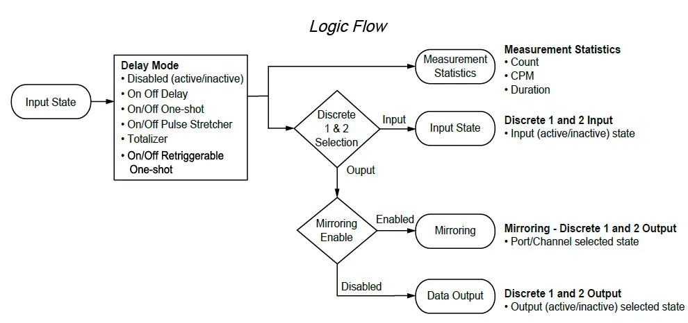
Discrete In/Out Configuration
Ports 1 through 4 contain discrete functionality. The figure below details the logic flow for each of the four bimodal discrete in/ out ports, and the tables define the configuration for each pin of the four bimodal ports.
Analog In/Out Configuration
Ports 5 through 8 contain analog functionality.
| Analog In
When an analog input value is received in Ports 5 through 8, the numerical representational value is sent to Modbus registers. Analog Input Ranges: • Voltage = 0 mV to 11,000 mV • Current = 0 µA to 24,000 µA |
Analog Out
Ports 5 through 8 also allow for the user to output an analog value by sending the numerical analog value to Modbus registers Analog Output Ranges: • Voltage = 0 mV to 10,000 mV • Current = 4000 µA to 20,000 µA |
Output Outside Valid Range (OOVR)
If the analog output value sent from this converter is outside of the Analog Output Range value, then the actual analog output value will be set to one of the three selectable OOVR levels after a 2-second delay: • Low (default): 0 V or 3.5 mA • High: 10.5 V or 20.5 mA • Hold: Level retains previous value indefinitely |
Modbus Configuration
Device Port States
| Modbus Register Address | Description | I/O Range | Comments | Default | Access | Notes |
|
40001 |
Active States |
0..255 |
Port 4..Port 1 → Pin 4[P#1] & Pin 2[P#2] Active States |
– |
RO |
0b[P42|P41|P32|P31|P22| P21|P12|P11] |
|
40002 |
Analog Input Active States |
0..15 |
Inactive = 0,
Active = 1 |
– |
RO |
0b[0|0|0|0|P8|P7|P6|P5] |
|
40003 |
Measurement Value
– Analog In Port 5 |
0..65535 |
Voltage = mV,
Current = µA |
– |
RO |
– |
|
40004 |
Measurement Value
– Analog In Port 6 |
0..65535 |
Voltage = mV,
Current = µA |
– |
RO |
– |
|
40005 |
Measurement Value
– Analog In Port 7 |
0..65535 |
Voltage = mV,
Current = µA |
– |
RO |
– |
|
40006 |
Measurement Value
– Analog In Port 8 |
0..65535 |
Voltage = mV,
Current = µA |
– |
RO |
– |
Analog Port Configuration
| Modbus Register Address | Description | I/O Range | Comments | Default | Access | Notes |
|
40007 |
Port 8-5 Analog-Out
| Port 8-5 Analog-In |
0..255 |
Voltage = 0,
Current = 1 |
0b11111111 |
RW |
0b[P8O|P7O|P6O|P5O] [P8I| P7I|P6I|P5I] |
Discrete Output States
| Modbus Register Address | Description | I/O Range | Comments | Default | Access | Notes |
|
40008 |
Output States |
0..255 |
Port 4..Port
1 → Pin 4[P#1] & Pin 2[P#2] Output States |
0b00000000 |
RW |
0b[P42|P41|P32|P31|P22| P21|P12|P11] |
Analog Out Value
| Modbus Register Address | Description | I/O Range | Comments | Default | Access | Notes |
|
40009 |
Port 5 – Analog Value |
0..20500 |
Voltage = mV,
Current = µA |
0 |
RW |
Max Voltage = 10000 mV, Max Current = 20000 µA |
|
40010 |
Port 6 – Analog Value |
0..20500 |
Voltage = mV,
Current = µA |
0 |
RW |
Max Voltage = 10000 mV, Max Current = 20000 µA |
|
40011 |
Port 7 – Analog Value |
0..20500 |
Voltage = mV,
Current = µA |
0 |
RW |
Max Voltage = 10000 mV, Max Current = 20000 µA |
|
40012 |
Port 8 – Analog Value |
0..20500 |
Voltage = mV,
Current = µA |
0 |
RW |
Max Voltage = 10000 mV, Max Current = 20000 µA |
Alias RO Registers
| Modbus Register Address | Description | I/O Range | Comments | Default | Access |
| 40501 | Port 5 Analog In | 0..65535 | Voltage = mV, Current = µA | – | RO |
| 40502 | Port 6 Analog In | 0..65535 | Voltage = mV, Current = µA | – | RO |
| 40503 | Port 7 Analog In | 0..65535 | Voltage = mV, Current = µA | – | RO |
| 40504 | Port 8 Analog In | 0..65535 | Voltage = mV, Current = µA | – | RO |
|
40505 |
Port 1 Pin 4 Active State |
0..1 |
0 = Inactive, 1 = Active |
– |
RO |
|
40506 |
Port 1 Pin 2 Active State |
0..1 |
0 = Inactive, 1 = Active |
– |
RO |
|
40507 |
Port 2 Pin 4 Active State |
0..1 |
0 = Inactive, 1 = Active |
– |
RO |
|
40508 |
Port 2 Pin 2 Active State |
0..1 |
0 = Inactive, 1 = Active |
– |
RO |
|
40509 |
Port 3 Pin 4 Active State |
0..1 |
0 = Inactive, 1 = Active |
– |
RO |
|
40510 |
Port 3 Pin 2 Active State |
0..1 |
0 = Inactive, 1 = Active |
– |
RO |
|
40511 |
Port 4 Pin 4 Active State |
0..1 |
0 = Inactive, 1 = Active |
– |
RO |
|
40512 |
Port 4 Pin 2 Active State |
0..1 |
0 = Inactive, 1 = Active |
– |
RO |
|
40513 |
Port 1 Pin 4 Count H |
0..65535 |
Port 1 Pin 4 Count Value Upper |
– |
RO |
|
40514 |
Port 1 Pin 4 Count L |
0..65535 |
Port 1 Pin 4 Count Value Lower |
– |
RO |
|
40515 |
Port 2 Pin 4 Count H |
0..65535 |
Port 1 Pin 4 Count Value Upper |
– |
RO |
|
40516 |
Port 2 Pin 4 Count L |
0..65535 |
Port 2 Pin 4 Count Value Lower |
– |
RO |
|
40517 |
Port 3 Pin 4 Count H |
0..65535 |
Port 1 Pin 4 Count Value Upper |
– |
RO |
|
40518 |
Port 3 Pin 4 Count L |
0..65535 |
Port 3 Pin 4 Count Value Lower |
– |
RO |
|
40519 |
Port 4 Pin 4 Count H |
0..65535 |
Port 1 Pin 4 Count Value Upper |
– |
RO |
|
40520 |
Port 4 Pin 4 Count L |
0..65535 |
Port 4 Pin 4 Count Value Lower |
– |
RO |
|
40521 |
Port 1 Pin 2 Count H |
0..65535 |
Port 1 Pin 4 Count Value Upper |
– |
RO |
|
40522 |
Port 1 Pin 2 Count L |
0..65535 |
Port 1 Pin 2 Count Value Lower |
– |
RO |
|
40523 |
Port 2 Pin 2 Count H |
0..65535 |
Port 1 Pin 4 Count Value Upper |
– |
RO |
|
40524 |
Port 2 Pin 2 Count L |
0..65535 |
Port 2 Pin 2 Count Value Lower |
– |
RO |
|
40525 |
Port 3 Pin 2 Count H |
0..65535 |
Port 1 Pin 4 Count Value Upper |
– |
RO |
|
40526 |
Port 3 Pin 2 Count L |
0..65535 |
Port 3 Pin 2 Count Value Lower |
– |
RO |
|
40527 |
Port 4 Pin 2 Count H |
0..65535 |
Port 1 Pin 4 Count Value Upper |
– |
RO |
|
40528 |
Port 4 Pin 2 Count L |
0..65535 |
Port 4 Pin 2 Count Value Lower |
– |
RO |
|
40529 |
Alias Register Value |
0..65535 |
User defined |
– |
RO |
|
40530 |
Alias Register Value |
0..65535 |
User defined |
– |
RO |
|
40531 |
Alias Register Value |
0..65535 |
User defined |
– |
RO |
|
40532 |
Alias Register Value |
0..65535 |
User defined |
– |
RO |
Alias Read/Only Addresses
| Modbus Register Address | Description | I/O Range | Comments | Register to Assign | Access |
|
40701 |
Alias Register Address |
0..65535 |
Value shows up in 40501 |
45001 |
RW |
|
40702 |
Alias Register Address |
0..65535 |
Value shows up in 40502 |
46001 |
RW |
|
40703 |
Alias Register Address |
0..65535 |
Value shows up in 40503 |
47001 |
RW |
|
40704 |
Alias Register Address |
0..65535 |
Value shows up in 40504 |
48001 |
RW |
|
40705 |
Alias Register Address |
0..65535 |
Value shows up in 40505 |
41001 |
RW |
|
40706 |
Alias Register Address |
0..65535 |
Value shows up in 40506 |
41002 |
RW |
|
40707 |
Alias Register Address |
0..65535 |
Value shows up in 40507 |
42001 |
RW |
|
40708 |
Alias Register Address |
0..65535 |
Value shows up in 40508 |
42002 |
RW |
|
40709 |
Alias Register Address |
0..65535 |
Value shows up in 40509 |
43001 |
RW |
|
40710 |
Alias Register Address |
0..65535 |
Value shows up in 40510 |
43002 |
RW |
|
40711 |
Alias Register Address |
0..65535 |
Value shows up in 40511 |
44001 |
RW |
|
40712 |
Alias Register Address |
0..65535 |
Value shows up in 40512 |
44002 |
RW |
|
40713 |
Alias Register Address |
0..65535 |
Value shows up in 40513 |
41003 |
RW |
|
40714 |
Alias Register Address |
0..65535 |
Value shows up in 40514 |
41004 |
RW |
|
40715 |
Alias Register Address |
0..65535 |
Value shows up in 40515 |
42003 |
RW |
|
40716 |
Alias Register Address |
0..65535 |
Value shows up in 40516 |
42004 |
RW |
|
40717 |
Alias Register Address |
0..65535 |
Value shows up in 40517 |
43003 |
RW |
|
40718 |
Alias Register Address |
0..65535 |
Value shows up in 40518 |
43004 |
RW |
|
40719 |
Alias Register Address |
0..65535 |
Value shows up in 40519 |
44003 |
RW |
|
40720 |
Alias Register Address |
0..65535 |
Value shows up in 40520 |
44004 |
RW |
|
40721 |
Alias Register Address |
0..65535 |
Value shows up in 40521 |
41011 |
RW |
|
40722 |
Alias Register Address |
0..65535 |
Value shows up in 40522 |
41012 |
RW |
|
40723 |
Alias Register Address |
0..65535 |
Value shows up in 40523 |
42011 |
RW |
|
40724 |
Alias Register Address |
0..65535 |
Value shows up in 40524 |
42012 |
RW |
|
40725 |
Alias Register Address |
0..65535 |
Value shows up in 40525 |
43011 |
RW |
|
40726 |
Alias Register Address |
0..65535 |
Value shows up in 40526 |
43012 |
RW |
|
40727 |
Alias Register Address |
0..65535 |
Value shows up in 40527 |
44011 |
RW |
|
40728 |
Alias Register Address |
0..65535 |
Value shows up in 40528 |
44012 |
RW |
|
40729 |
Alias Register Address |
0..65535 |
Value shows up in 40529 |
0 |
RW |
|
40730 |
Alias Register Address |
0..65535 |
Value shows up in 40530 |
0 |
RW |
|
40731 |
Alias Register Address |
0..65535 |
Value shows up in 40531 |
0 |
RW |
|
40732 |
Alias Register Address |
0..65535 |
Value shows up in 40532 |
0 |
RW |
Alias RW Registers
| Modbus Register Address | Description | I/O Range | Comments | Default | Access |
|
40801 |
Port 1 Pin 4 Active State |
0..1 |
0 = Inactive, 1 = Active |
– |
RW |
|
40802 |
Port 1 Pin 2 Active State |
0..1 |
0 = Inactive, 1 = Active |
– |
RW |
|
40803 |
Port 2 Pin 4 Active State |
0..1 |
0 = Inactive, 1 = Active |
– |
RW |
|
40804 |
Port 2 Pin 2 Active State |
0..1 |
0 = Inactive, 1 = Active |
– |
RW |
|
40805 |
Port 3 Pin 4 Active State |
0..1 |
0 = Inactive, 1 = Active |
– |
RW |
|
40806 |
Port 3 Pin 2 Active State |
0..1 |
0 = Inactive, 1 = Active |
– |
RW |
|
40807 |
Port 4 Pin 4 Active State |
0..1 |
0 = Inactive, 1 = Active |
– |
RW |
|
40808 |
Port 4 Pin 2 Active State |
0..1 |
0 = Inactive, 1 = Active |
– |
RW |
| 40809 | Port 5 Analog Out | 0..65535 | Voltage = mV, Current = µA | – | RW |
| 40810 | Port 6 Analog Out | 0..65535 | Voltage = mV, Current = µA | – | RW |
| 40811 | Port 7 Analog Out | 0..65535 | Voltage = mV, Current = µA | – | RW |
| 40812 | Port 8 Analog Out | 0..65535 | Voltage = mV, Current = µA | – | RW |
|
40813 |
Alias RW Register Value |
0..65535 |
User defined |
– |
RW |
|
40814 |
Alias RW Register Value |
0..65535 |
User defined |
– |
RW |
|
40815 |
Alias RW Register Value |
0..65535 |
User defined |
– |
RW |
|
40816 |
Alias RW Register Value |
0..65535 |
User defined |
– |
RW |
|
40817 |
Alias RW Register Value |
0..65535 |
User defined |
– |
RW |
|
40818 |
Alias RW Register Value |
0..65535 |
User defined |
– |
RW |
|
40819 |
Alias RW Register Value |
0..65535 |
User defined |
– |
RW |
|
40820 |
Alias RW Register Value |
0..65535 |
User defined |
– |
RW |
|
40821 |
Alias RW Register Value |
0..65535 |
User defined |
– |
RW |
|
40822 |
Alias RW Register Value |
0..65535 |
User defined |
– |
RW |
|
40823 |
Alias RW Register Value |
0..65535 |
User defined |
– |
RW |
|
40824 |
Alias RW Register Value |
0..65535 |
User defined |
– |
RW |
|
40825 |
Alias RW Register Value |
0..65535 |
User defined |
– |
RW |
|
40826 |
Alias RW Register Value |
0..65535 |
User defined |
– |
RW |
|
40827 |
Alias RW Register Value |
0..65535 |
User defined |
– |
RW |
|
40828 |
Alias RW Register Value |
0..65535 |
User defined |
– |
RW |
|
40829 |
Alias RW Register Value |
0..65535 |
User defined |
– |
RW |
|
40830 |
Alias RW Register Value |
0..65535 |
User defined |
– |
RW |
|
40831 |
Alias RW Register Value |
0..65535 |
User defined |
– |
RW |
|
40832 |
Alias RW Register Value |
0..65535 |
User defined |
– |
RW |
Alias Read/Write Addresses
| Modbus Register Address |
Description |
I/O Range |
Comments |
Register to Assign |
Access |
|
40901 |
Alias Register Address |
0..65535 |
Value shows up in 40801 |
41401 |
RW |
|
40902 |
Alias Register Address |
0..65535 |
Value shows up in 40802 |
41402 |
RW |
|
40903 |
Alias Register Address |
0..65535 |
Value shows up in 40803 |
42401 |
RW |
|
40904 |
Alias Register Address |
0..65535 |
Value shows up in 40804 |
42402 |
RW |
|
40905 |
Alias Register Address |
0..65535 |
Value shows up in 40805 |
43401 |
RW |
|
40906 |
Alias Register Address |
0..65535 |
Value shows up in 40806 |
43402 |
RW |
|
40907 |
Alias Register Address |
0..65535 |
Value shows up in 40807 |
44401 |
RW |
|
40908 |
Alias Register Address |
0..65535 |
Value shows up in 40808 |
44402 |
RW |
|
40909 |
Alias Register Address |
0..65535 |
Value shows up in 40809 |
45002 |
RW |
|
40910 |
Alias Register Address |
0..65535 |
Value shows up in 40810 |
46002 |
RW |
|
40911 |
Alias Register Address |
0..65535 |
Value shows up in 40811 |
47002 |
RW |
|
40912 |
Alias Register Address |
0..65535 |
Value shows up in 40812 |
48002 |
RW |
|
40913 |
Alias Register Address |
0..65535 |
Value shows up in 40813 |
0 |
RW |
|
40914 |
Alias Register Address |
0..65535 |
Value shows up in 40814 |
0 |
RW |
|
40915 |
Alias Register Address |
0..65535 |
Value shows up in 40815 |
0 |
RW |
|
40916 |
Alias Register Address |
0..65535 |
Value shows up in 40816 |
0 |
RW |
|
40917 |
Alias Register Address |
0..65535 |
Value shows up in 40817 |
0 |
RW |
|
40918 |
Alias Register Address |
0..65535 |
Value shows up in 40818 |
0 |
RW |
|
40919 |
Alias Register Address |
0..65535 |
Value shows up in 40819 |
0 |
RW |
|
40920 |
Alias Register Address |
0..65535 |
Value shows up in 40820 |
0 |
RW |
|
40921 |
Alias Register Address |
0..65535 |
Value shows up in 40821 |
0 |
RW |
|
40922 |
Alias Register Address |
0..65535 |
Value shows up in 40822 |
0 |
RW |
|
40923 |
Alias Register Address |
0..65535 |
Value shows up in 40823 |
0 |
RW |
|
40924 |
Alias Register Address |
0..65535 |
Value shows up in 40824 |
0 |
RW |
|
40925 |
Alias Register Address |
0..65535 |
Value shows up in 40825 |
0 |
RW |
|
40926 |
Alias Register Address |
0..65535 |
Value shows up in 40826 |
0 |
RW |
|
40927 |
Alias Register Address |
0..65535 |
Value shows up in 40827 |
0 |
RW |
|
40928 |
Alias Register Address |
0..65535 |
Value shows up in 40828 |
0 |
RW |
|
40929 |
Alias Register Address |
0..65535 |
Value shows up in 40829 |
0 |
RW |
|
40930 |
Alias Register Address |
0..65535 |
Value shows up in 40830 |
0 |
RW |
|
40931 |
Alias Register Address |
0..65535 |
Value shows up in 40831 |
0 |
RW |
|
40932 |
Alias Register Address |
0..65535 |
Value shows up in 40832 |
0 |
RW |
Modbus Configuration
| Modbus Register Address | Description | I/O Range | Comments | Default | Access |
|
40601 |
Baud Rate |
0 = 9.6k
1 = 19.2k 2 = 38.4k |
0 = 9600
1 = 19200 2 = 38400 |
1 |
RW |
|
40602 |
Parity |
0 = None
1 = Odd 2 = Even |
0 = None
1 = Odd 2 = Even |
0 |
RW |
| 40603 | Address | 1-254 | – | 1 | RW |
|
40604 |
Reserved (cannot be read or written) |
None |
– |
– |
– |
|
40605 |
Restore Factory Configuration | 0 = No Operation, 1 = Restore |
– |
– |
WO |
Device Information
| Modbus Register Address | Description | I/O Range | Comments | Default | Access | Notes |
| 40606-40615 | Banner Name | 0..65535 | – | Banner Engineering | RO | (9 words/18 characters) |
| 40616-40631 | Product Name | 0..65535 | – | R95C-4B4UI-MQ | RO | (16 words/32 characters) |
| 40632 | Item H | 0..65535 | 814993 split into two 16-bit registers | 12 | RO | Banner Item Number |
| 40633 | Item L | 0..65535 | 28561 | RO | – | |
| 40634 | Serial Number H | 0..65535 | – | – | RO |
Serial Number is split into four 16-bit registers |
| 40635 | Serial Number | 0..65535 | – | – | RO | |
| 40636 | Serial Number | 0..65535 | – | – | RO | |
| 40637 | Serial Number L | 0..65535 | – | – | RO | |
|
40644-40659 |
User Define Tag |
0..65535 |
User writable space | More Sensors. More Solutions. |
RW |
(16 words/32 characters) |
|
40680 |
Discovery |
0..1 |
0 = Disabled, 1
= Enabled |
– |
RW |
Flash all LEDs to find hub |
|
40681 |
All-Time Run Time H |
0..65535 |
– |
– |
RO |
Upper 16 of 32 bits |
|
40682 |
All-Time Run Time L |
0..65535 |
Run counter (0.25 hr) |
– |
RO |
Lower 16 of 32 bits |
|
40683 |
Resettable Run Time H |
0..65535 |
– |
– |
RW |
Upper 16 of 32 bits |
|
40684 |
Resettable Run Time L |
0..65535 |
Run counter (0.25 hr) |
– |
RW |
Lower 16 of 32 bits |
Multi-Port Support Ports 1-4
Register Ranges for Ports 1-4
| Register Ranges | Port Number |
| 41001-41400 | Port 1 |
| 42001-42400 | Port 2 |
| 43001-43400 | Port 3 |
| 44001-44400 | Port 4 |
Measurement Reads
| Modbus Register Address | Description | I/O Range | Comments | Default | Access | Notes |
|
41001 |
Port 1 Pin 4 Active State |
0..1 |
0 = Inactive, 1 = Active |
– |
RO |
– |
|
41002 |
Port 1 Pin 2 Active State |
0..1 |
0 = Inactive, 1 = Active |
– |
RO |
– |
|
41003 |
Pin 4 Count H |
0..65535 |
Pin 4 Count Value Upper |
– |
RO |
Upper 16 of 32 bits = Running count of the received input pulses |
|
41004 |
Pin 4 Count L |
0..65535 |
Pin 4 Count Value Lower |
– |
RO |
Lower 16 of 32 bits = Running count of the received input pulses |
|
41005 |
Pin 4 Duration H |
0..65535 |
Pin 4 Duration Value Upper |
– |
RO |
Upper 16 of 32 bits = Duration of the last input pulse in µs with 50 µs granularity |
|
41006 |
Pin 4 Duration L |
0..65535 |
Pin 4 Duration Value Lower |
– |
RO |
Lower 16 of 32 bits = Duration of the last input pulse in µs with 50 µs granularity |
|
41007 |
Pin 4 Counts Per Minute H |
0..65535 |
Pin 4 Counts Per Minute Value Upper |
– |
RO |
Upper 16 of 32 bits = Running count of the number of pulses received averaged over one minute. Range 1 to 37,500 |
|
41008 |
Pin 4 Counts Per Minute L |
0..65535 |
Pin 4 Counts Per Minute Value Lower |
– |
RO |
Lower 16 of 32 bits = Running count of the number of pulses received averaged over one minute. Range 1 to 37,500 |
|
41009 |
Pin 4 Totalizer Count H |
0..65535 |
Pin 4 Totalizer Count Upper |
– |
RO |
Upper 16 of 32 bits = Totalizer count |
|
41010 |
Pin 4 Totalizer Count L |
0..65535 |
Pin 4 Totalizer Count Lower |
– |
RO |
Lower 16 of 32 bits = Totalizer count |
|
41011 |
Pin 2 Count H |
0..65535 |
Pin 2 Count Value Upper |
– |
RO |
Upper 16 of 32 bits = Running count of the received input pulses |
|
41012 |
Pin 2 Count L |
0..65535 |
Pin 2 Count Value Lower |
– |
RO |
Lower 16 of 32 bits = Running count of the received input pulses |
|
41013 |
Pin 2 Duration H |
0..65535 |
Pin 2 Duration Value Upper |
– |
RO |
Upper 16 of 32 bits = Duration of the last input pulse in µs with 50 µs granularity |
|
41014 |
Pin 2 Duration L |
0..65535 |
Pin 2 Duration Value Lower |
– |
RO |
Lower 16 of 32 bits = Duration of the last input pulse in µs with 50 µs granularity |
|
41015 |
Pin 2 Counts Per Minute H |
0..65535 |
Pin 2 Counts Per Minute Value Upper |
– |
RO |
Upper 16 of 32 bits = Running count of the number of pulses received averaged over one minute. Range 1 to 37,500 |
|
41016 |
Pin 2 Counts Per Minute L |
0..65535 |
Pin 2 Counts Per Minute Value Lower |
– |
RO |
Lower 16 of 32 bits = Running count of the number of pulses received averaged over one minute. Range 1 to 37,500 |
|
41017 |
Pin 2 Totalizer Count H |
0..65535 |
Pin 2 Totalizer Count Upper |
– |
RO |
Upper 16 of 32 bits = Totalizer count |
|
41018 |
Pin 2 Totalizer Count L |
0..65535 |
Pin 2 Totalizer Count Lower |
– |
RO |
Lower 16 of 32 bits = Totalizer count |
Measurement Count Presets: these registers reset ALL measurements, not just the count values
| Modbus Register Address | Description | I/O Range | Comments | Default | Access | Notes |
|
41100 |
Pin 4 Count H |
0..65535 |
Pin 4 Count Value Upper |
– |
RW |
Upper 16 of 32 bits |
|
41101 |
Pin 4 Count L |
0..65535 |
Pin 4 Count Value Lower |
– |
RW |
Lower 16 of 32 bits |
|
41102 |
Pin 2 Count H |
0..65535 |
Pin 2 Count Value Upper |
– |
RW |
Upper 16 of 32 bits |
|
41103 |
Pin 2 Count L |
0..65535 |
Pin 2 Count Value Lower |
– |
RW |
Lower 16 of 32 bits |
Pin 4 Port Configuration (Black – Female, Discrete 1)
| Modbus Register Address |
Description |
I/O Range |
Comments |
Default |
Access |
Notes |
|
41200 |
Pin 4 IO Selection |
0..5 |
0 = NPN input 1 = PNP input
2 = NPN output with pull up 3 = PNP output with pull down 4 = NPN output push/pull 5 = PNP output push/pull |
3 |
RW |
– |
|
41201 |
Pin 4 Mode |
0..8 |
0 = Disabled
1 = On Off Delay 2 = On One-shot 3 = Off One-shot 4 = On Pulse-stretcher 5 = Off Pulse-stretcher 6 = Totalizer 7 = Retriggerable On One-shot 8 = Retriggerable Off One-shot |
0 |
RW |
– |
|
41202 |
Pin 4 Delay Timer 1 Upper |
0..65535 |
Pin 4 On Delay, One-shot, Pulse- stretcher time, Totalizer Count |
0 |
RW |
Upper 16 of 32 Bits:
Mode 1, 2, 3, 4, 5, 7, 8 = Milliseconds
Mode 6 = Count |
|
41203 |
Pin 4 Delay Timer 1 Lower |
0..65535 |
Pin 4 On Delay, One-shot, Pulse- stretcher time, Totalizer Count |
0 |
RW |
Lower 16 of 32 Bits:
Mode 1, 2, 3, 4, 5, 7, 8 = Milliseconds
Mode 6 = Count |
|
41204 |
Pin 4 Delay Timer 2 Upper |
0..65535 |
Pin 4 Off Delay or Totalizer time |
0 |
RW |
Upper 16 of 32 Bits = Milliseconds |
|
41205 |
Pin 4 Delay Timer 2 Lower |
0..65535 |
Pin 4 Off Delay or Totalizer time |
0 |
RW |
Lower 16 of 32 Bits = Milliseconds |
| 41206 | Pin 4 Mirroring Enable | 0..1 | 0 = Disabled, 1 = Enabled | 0 | RW | – |
|
41207 |
Pin 4 Mirroring Port Selection |
0..7 |
0 = Port 1
1 = Port 2 2 = Port 3 3 = Port 4 4 = Port 5 5 = Port 6 6 = Port 7 7 = Port 8 |
0 |
RW |
If Port 1-4, Discrete Mirroring
If Port 5-8, PFM of Analog In |
|
41208 |
Pin 4 Mirroring Selection |
0..1 |
0 = Channel 1, 1 = Channel 2 |
0 |
RW |
If Port 1-4, Discrete Mirroring |
|
41209 |
Pin 4 Mirroring Inversion |
0..1 |
0 = Not inverted, 1 = Inverted |
0 |
RW |
If Port 1-4, Discrete Mirroring |
|
41210 |
Pin 4 PFM Near Frequency (Hz) |
100..600 |
– |
100 |
RW |
If Port 5-8, PFM of Analog In |
|
41211 |
Pin 4 PFM Far Frequency (Hz) |
100..600 |
– |
600 |
RW |
If Port 5-8, PFM of Analog In |
Pin 2 Port Configuration (White – Female, Discrete 2)
| Modbus Register Address |
Description |
I/O Range |
Comments |
Default |
Access |
Notes |
|
41300 |
Pin 2 IO Selection |
0..5 |
0 = NPN input 1 = PNP input
2 = NPN output with pull up 3 = PNP output with pull down 4 = NPN output push/pull 5 = PNP output push/pull |
3 |
RW |
– |
|
41301 |
Pin 2 Mode |
0..6 |
0 = Disabled
1 = On Off Delay 2 = On One-shot 3 = Off One-shot 4 = On Pulse-stretcher 5 = Off Pulse-stretcher 6 = Totalizer 7 = Retriggerable On One-shot 8 = Retriggerable Off One-shot |
0 |
RW |
– |
|
41302 |
Pin 2 Delay Timer 1 Upper |
0..65535 |
Pin 2 On Delay, One-shot, Pulse- stretcher time, or Totalizer Count |
0 |
RW |
Upper 16 of 32 Bits:
Mode 1, 2, 3, 4, 5, 7, 8 = Milliseconds
Mode 6 = Count |
|
41303 |
Pin 2 Delay Timer 1 Lower |
0..65535 |
Pin 2 On Delay, One-shot, Pulse- stretcher time, or Totalizer Count |
0 |
RW |
Lower 16 of 32 Bits:
Mode 1, 2, 3, 4, 5, 7, 8 = Milliseconds
Mode 6 = Count |
|
41304 |
Pin 2 Delay Timer 2 Upper |
0..65535 |
Pin 2 Off Delay or Totalizer time |
0 |
RW |
Upper 16 of 32 Bits = Milliseconds |
|
41305 |
Pin 2 Delay Timer 2 Lower |
0..65535 |
Pin 2 Off Delay or Totalizer time |
0 |
RW |
Lower 16 of 32 Bits = Milliseconds |
| 41306 | Pin 2 Mirroring Enable | 0..1 | 0 = Disabled, 1 = Enabled | 0 | RW | – |
|
41307 |
Pin 2 Mirroring Port Selection |
0..7 |
0 = Port 1
1 = Port 2 2 = Port 3 3 = Port 4 4 = Port 5 5 = Port 6 6 = Port 7 7 = Port 8 |
0 |
RW |
If Port 1-4, Discrete Mirroring
If Port 5-8, PFM of Analog In |
|
41308 |
Pin 2 Mirroring Selection |
0..1 |
0 = Channel 1, 1 = Channel 2 |
0 |
RW |
If Port 1-4, Discrete Mirroring |
|
41309 |
Pin 2 Mirroring Inversion |
0..1 |
0 = Not Inverted, 1 = Inverted |
0 |
RW |
If Port 1-4, Discrete Mirroring |
|
41310 |
Pin 2 PFM Near Frequency (Hz) |
100..600 |
– |
100 |
RW |
If Port 5-8, PFM of Analog In |
|
41311 |
Pin 2 PFM Far Frequency (Hz) |
100..600 |
– |
600 |
RW |
If Port 5-8, PFM of Analog In |
Active Configurations
| Modbus Register Address |
Description |
I/O Range |
Comments |
Default |
Access |
Notes |
|
41401 |
Port 1 Pin 4 Active State |
0..1 |
0 = Inactive, 1 = Active |
0 |
RW |
If mirroring disabled & IO selection is output, Data Output set to inactive/active |
|
41402 |
Port 1 Pin 2 Active State |
0..1 |
0 = Inactive, 1 = Active |
0 |
RW |
If mirroring disabled & IO selection is output, Data Output set to inactive/active |
Multi-Port Support Ports 5-8
Register Ranges for Ports 5-8
| Register Ranges | Port Number |
| 45001-45305 | Port 5 |
| 46001-46305 | Port 6 |
| 47001-47305 | Port 7 |
| 48001-48305 | Port 8 |
Measurement Reads
| Modbus Register Address | Description | I/O Range | Comments | Default | Access | Notes |
|
45001 |
Measurement Value
– Analog In Port 5 |
0..65535 |
Voltage = mV,
Current = µA |
– |
RO |
– |
|
45002 |
Port 5 – Analog Out |
0..20500 |
Voltage = mV,
Current = µA |
0 |
RW |
Voltage = 10000 mV, Current
= 20000 µA |
Port Output Configuration (Black – Channel 1)
| Modbus Register Address | Description | I/O Range | Comments | Default | Access | Notes |
|
45200 |
Port 5 – Mirroring Output Enable |
0..1 |
0 = Disabled, 1 = Enabled |
0 |
RW |
If Enabled, Analog Out value in register 40009 will be ignored |
|
45201 |
Port 5 – Mirroring Input Port Selection |
0..1 |
0 = Port 5
1 = Port 6 2 = Port 7 3 = Port 8 |
0 |
RW |
– |
|
45202 |
Port 5 – Output Outside of Valid Range |
0..2 |
0 = Hold, 1 = Low, 2 = High |
1 |
RW |
– |
Port Output Configuration (White – Channel 2)
| Modbus Register Address | Description | I/O Range | Comments | Default | Access | Notes |
|
45300 |
Port 5 – Voltage Minimum LED setpoint value |
0..9999 |
Must be less than maximum. |
V = 0 mV |
RW |
– |
|
45301 |
Port 5 – Voltage Maximum LED setpoint value |
0..10000 |
Must be greater than minimum. |
V = 10000 mV |
RW |
If value > Max I/O Range, value = Max |
|
45302 |
Port 5 – Voltage Hysteresis |
0..500 |
mV |
V = 50 mV |
RW |
If value > Max I/O Range, value = Max |
|
45303 |
Port 5 – Current Minimum LED setpoint value |
0..19999 |
Must be less than maximum. |
4000 µA |
RW |
– |
|
45304 |
Port 5 – Current Maximum LED setpoint value |
0..20000 |
Must be greater than minimum. |
20000 µA |
RW |
If value > Max I/O Range, value = Max |
|
45305 |
Port 5 – Current Hysteresis |
0..500 |
µA |
100 µA |
RW |
If value > Max I/O Range, value = Max |
Mechanical Installation
Install the R95C to allow access for functional checks, maintenance, and service or replacement. Do not install the R95C in such a way to allow for intentional defeat.
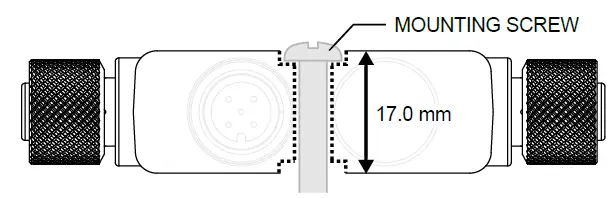
Fasteners must be of sufficient strength to guard against breakage. The use of permanent fasteners or locking hardware is recommended to prevent the loosening or displacement of the device. The mounting hole (4.5 mm) in the R95C accepts M4 (#8) hardware.
See the figure below to help in determining the minimum screw length.
CAUTION
- Do not overtighten the R95C’s mounting screw during installation.
- Overtightening can affect the performance of the R95C.
Wiring
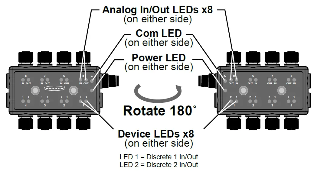
Status Indicators
On both sides of the R95C Modbus hub, Ports 1 through 4 have two matching amber LED discrete output indicators, and Ports 5 through 8 have two matching amber LED analog in/analog out indicators. There is also an additional amber LED indicator on both sides of the converter, which is specific to the Modbus communication, and a green LED indicator that shows power status.
| LED | Indication | Status |
| Discrete Device Amber LEDs | Off | Discrete In and Out are inactive |
| Solid Amber | Discrete In or Out is active | |
|
Analog In Amber LED(1) |
Off | Analog current value is less than setpoint one OR analog value is greater than setpoint two |
| Solid Amber | Analog current value is between setpoint one AND setpoint two | |
|
Analog Out Amber LED |
Off |
Turns off if written PDO analog value is outside the allowable output range
Allowable Voltage Range: 0 V to 10 V. Allowable Current Range: 4 mA to 20 mA. |
|
Solid Amber |
Turns on if written PDO analog value is inside the allowable output range
Allowable Voltage Range: 0 V to 10 V. Allowable Current Range: 4 mA to 20 mA. |
|
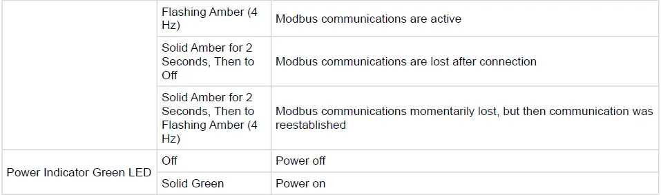
| Modbus Communication Amber LED | Off | Modbus communications are not present |
(1) Default Current Values: SP1 = 0.004 A, SP2 = 0.02 A. Default Voltage values: SP1 = 0 V, SP2 = 10 V.
Specifications
- Supply Voltage
- 12 V DC to 30 V DC at 400 mA maximum (exclusive of load)
- Power Pass-Through Current
- Not to exceed 4 amps total
- Discrete Output Load Rating
- 200 mA
- Analog Input Impedance
- Current version: Approximately 250 Ω
- Voltage version: Approximately 14.3k Ω
- Analog Output Load Requirements
- Voltage version = Resistance > 1000 Ω
- Current version = Resistance < 500 Ω
- Supply Protection Circuitry
- Protected against reverse polarity and transient voltages
- Leakage Current Immunity
- 400 μA
- Indicators
- Green: Power
- Amber: Modbus communications
- Amber: 2x Discrete IN/OUT status
- Amber: Analog input value present
- Amber: Analog output value in range
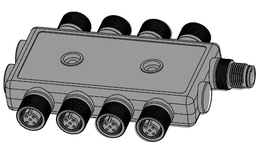
- Connections
- (8) Integral 4-pin M12 female quick-disconnect connectors
- (1) Integral 5-pin M12 male quick-disconnect connector
- Construction
- Coupling Material: Nickel-plated brass
- Connector Body: PVC translucent black
- Vibration and Mechanical Shock
- Meets IEC 60068-2-6 requirements (Vibration: 10 Hz to 55 Hz, 0.5 mm amplitude, 5 minutes sweep, 30 minutes dwell)
- Meets IEC 60068-2-27 requirements (Shock: 15G 11 ms duration, half sine wave)
- Environmental Rating
- IP65, IP67, IP68
- UL Type 1
- Operating Conditions
- Temperature: –40 °C to +70 °C (–40 °F to +158 °F)
- 90% at +70 °C maximum relative humidity (non-condensing)
- Storage Temperature: –40 °C to +80 °C (–40 °F to +176 °F)
- Temperature: –40 °C to +70 °C (–40 °F to +158 °F)
Required Overcurrent Protection
WARNING: Electrical connections must be made by qualified personnel in accordance with local and national electrical codes and regulations.
Overcurrent protection is required to be provided by end product application per the supplied table.
Overcurrent protection may be provided with external fusing or via Current Limiting, Class 2 Power Supply.
Supply wiring leads < 24 AWG shall not be spliced.
For additional product support, go to www.bannerengineering.com.
| Supply Wiring (AWG) |
Required Overcurrent Protection (A) |
Supply Wiring (AWG) |
Required Overcurrent Protection (A) |
| 20 | 5.0 | 26 | 1.0 |
| 22 | 3.0 | 28 | 0.8 |
| 24 | 1.0 | 30 | 0.5 |
Certifications

Product Identification

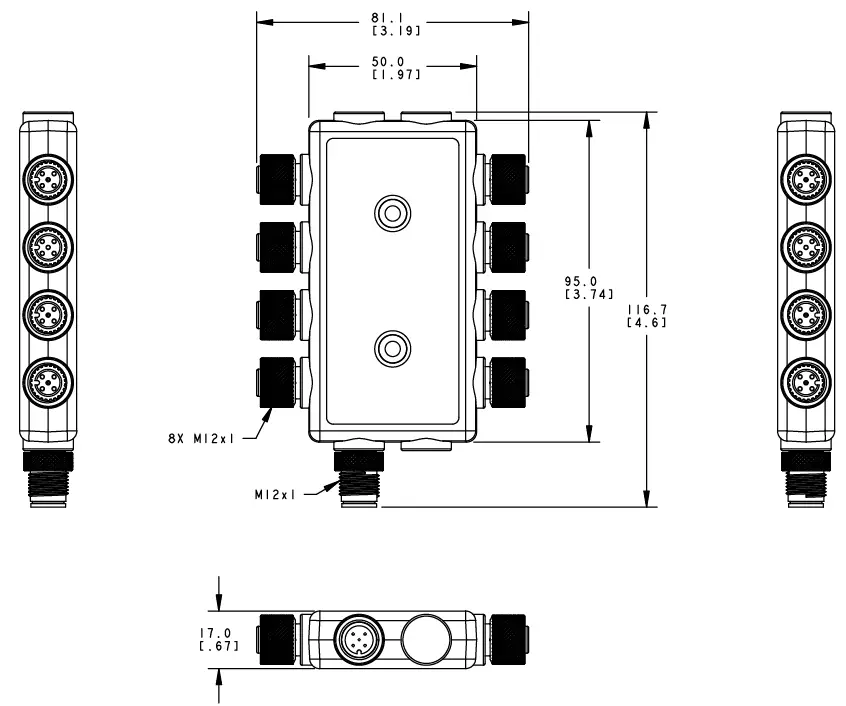
Dimensions
All measurements are listed in millimeters [inches], unless noted otherwise.
FCC STATEMENT
FCC Part 15 Class B for Unintentional Radiators
(Part 15.105(b))
This equipment has been tested and found to comply with the limits for a Class B digital device, pursuant to part 15 of the FCC Rules. These limits are designed to provide reasonable protection against harmful interference in a residential installation. This equipment generates, uses, and can radiate radio frequency energy and, if not installed and used in accordance with the instructions, may cause harmful interference to radio communications. However, there is no guarantee that interference will not occur in a particular installation. If this equipment does cause harmful interference to radio or television reception, which can be determined by turning the equipment off and on, the user is encouraged to try to correct the interference by one or more of the following measures:
- Reorient or relocate the receiving antenna.
- Increase the separation between the equipment and receiver.
- Connect the equipment into an outlet on a circuit different from that to which the receiver is connected.
- Consult the dealer or an experienced radio/TV technician for help.
(Part 15.21)
- Any changes or modifications not expressly approved by the party responsible for compliance could void the user’s authority to operate this equipment.
Industry Canada ICES-003(B)
This device complies with CAN ICES-3 (B)/NMB-3(B). Operation is subject to the following two conditions:
- This device may not cause harmful interference;
- This device must accept any interference received, including interference that may cause undesired operation.
R95C Accessories
Cordsets
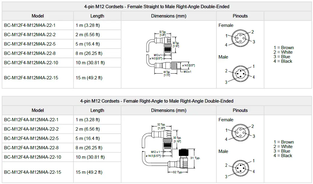
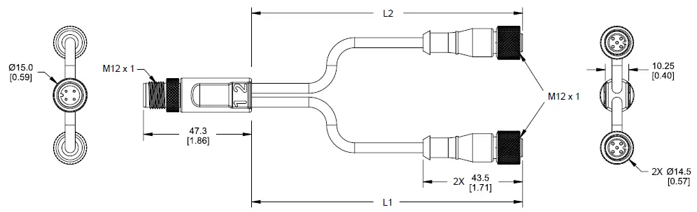
| 4-Pin Threaded M12 Male to 5-Pin Threaded M12 Female Splitter Cordset | ||
| Model | Branches (Female) | Wiring |
|
S15YA4-M124-M124-0.2M |
L1, L2 2 × 0.2 m (7.9 in) |
 |
| 4-Pin Threaded M12 Male to 5-Pin Threaded M12 Female Splitter Cordset | ||
| Model | Branches (Female) | Wiring |
 |
||
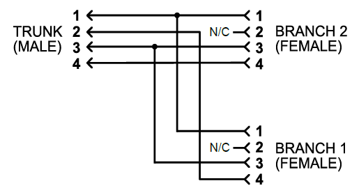
5-Pin Threaded M12 Splitter Cordset with Flat Junction—Double Ended
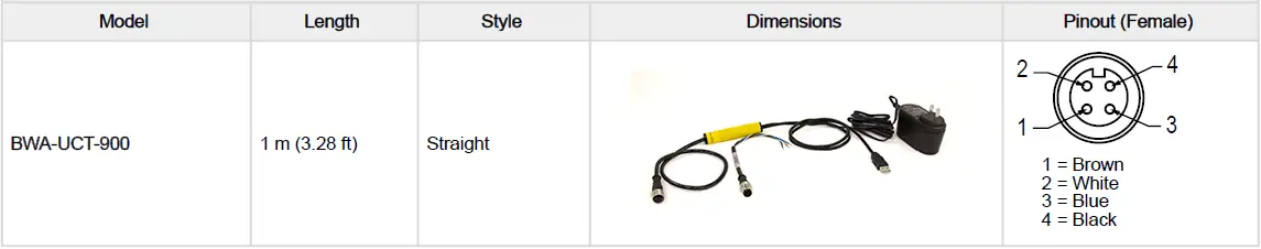
4-Pin Threaded M12 RS-485 to USB Adapter Cordset, with Wall Plug
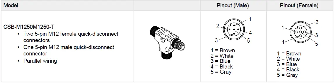
Splitter Tee
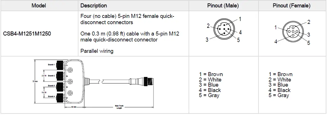
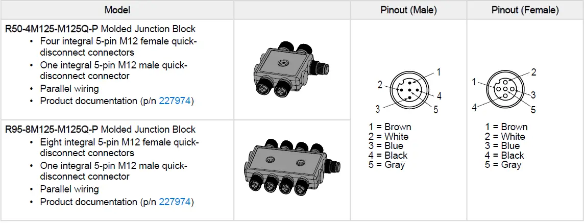
5-Pin Molded Junction Blocks
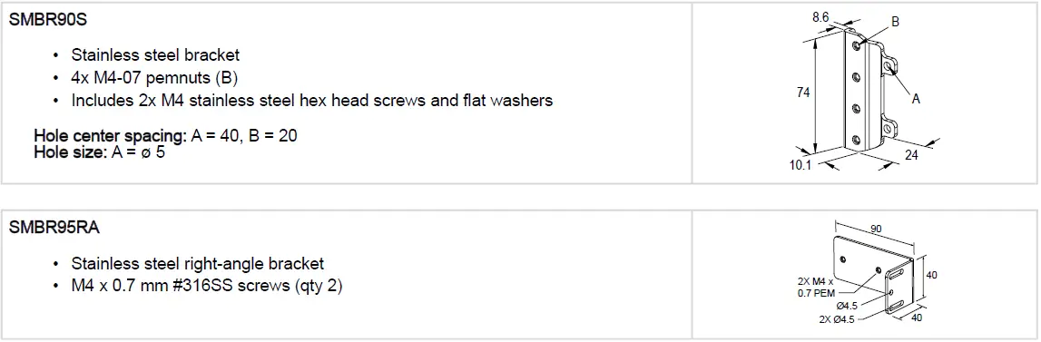
Brackets
Limited Warranty
Banner Engineering Corp Limited Warranty
Banner Engineering Corp. warrants its products to be free from defects in material and workmanship for one year following the date of shipment. Banner Engineering Corp. will repair or replace, free of charge, any product of its manufacture which, at the time it is returned to the factory, is found to have been defective during the warranty period. This warranty does not cover damage or liability for misuse, abuse, or the improper application or installation of the Banner product.
THIS LIMITED WARRANTY IS EXCLUSIVE AND IN LIEU OF ALL OTHER WARRANTIES WHETHER EXPRESS OR IMPLIED (INCLUDING, WITHOUT LIMITATION, ANY WARRANTY OF MERCHANTABILITY OR FITNESS FOR A PARTICULAR PURPOSE), AND WHETHER ARISING UNDER COURSE OF PERFORMANCE, COURSE OF DEALING OR TRADE USAGE.
This Warranty is exclusive and limited to repair or, at the discretion of Banner Engineering Corp., replacement. IN NO EVENT SHALL BANNER ENGINEERING CORP. BE LIABLE TO BUYER OR ANY OTHER PERSON OR ENTITY FOR ANY EXTRA COSTS, EXPENSES, LOSSES, LOSS OF PROFITS, OR ANY INCIDENTAL, CONSEQUENTIAL OR SPECIAL DAMAGES RESULTING FROM ANY PRODUCT DEFECT OR FROM THE USE OR INABILITY TO USE THE PRODUCT, WHETHER ARISING IN CONTRACT OR WARRANTY, STATUTE, TORT, STRICT LIABILITY, NEGLIGENCE, OR OTHERWISE.
Banner Engineering Corp. reserves the right to change, modify or improve the design of the product without assuming any obligations or liabilities relating to any product previously manufactured by Banner Engineering Corp. Any misuse, abuse, or improper application or installation of this product or use of the product for personal protection applications when the product is identified as not intended for such purposes will void the product warranty. Any modifications to this product without prior express approval by Banner Engineering Corp will void the product warranties. All specifications published in this document are subject to change; Banner reserves the right to modify product specifications or update documentation at any time. Specifications and product information in English supersede that which is provided in any other language. For the most recent version of any documentation, refer to: www.bannerengineering.com.
For patent information, see www.bannerengineering.com/patents.
More Information
© 2024. All rights reserved.
www.bannerengineering.com
© Banner Engineering Corp. All rights reserved.
Documents / Resources
 |
BANNER R95C 8-Port 2-Channel Discrete and Analog In-Out Modbus Hub [pdf] Instruction Manual R95C-4B4UI-MQ, R95C Modbus Hubs, R95C 8-Port 2-Channel Discrete and Analog In-Out Modbus Hub, R95C, 8-Port 2-Channel Discrete and Analog In-Out Modbus Hub, 8-Port 2-Channel Discrete, 2-Channel Discrete, Discrete, 2-Channel Discrete and Analog In-Out Modbus Hub, Analog In-Out Modbus Hub, Analog Modbus Hub, In-Out Modbus Hub, Modbus Hub, Modbus, Hub |


