![]()
DS3231 Real Time Clock Module
Welcome!
Thank you for purchasing our AZ-Delivery DS3231 Real Time Clock Module.
On the following pages, you will be introduced to how to use and set up this handy device.
Have fun!

Introduction
The DS3231 Real Time Clock module is used as time synchronization device in applications where precise timings are essential. The module is used in digital clocks, computer motherboards, digital cameras, embedded systems etc.
It is a real time clock with an integrated temperature-compensated crystal oscillator. There is an on-board battery holder, so that it can maintain continuous time keeping when the device is not powered from an external source.
One of the features of the module is that it can operate in 12 hour or 24 hour format and has a AM/PM indication capability.
The module is programmable with two day-time alarms. Alarms can be programmed via an integrated EEPROM chip which can store alarm data in internal memory. There is also 32KHz square-wave oscillator output pin, which can be used to synchronize time with other similar devices.
The internal clock can provide seconds, minutes, hours, day, date, month, and year information. The date at the end of the month is automatically adjusted for months which have less than 31 days. It also includescorrections for leap years.
The module has an I2C interface with I2C serial address, and it can be connected alongside with other devices on the same I2C lines.
Specifications
| Power supply voltage | 3.3V |
| Operational temperature | from 0℃ to +70℃ |
| Communication interface | I2C |
| Battery backup | One 3V coin cell battery batter holder |
| Digital temp sensor | ±3°C Accuracy |
| Programmable square-wave | 32kHz [Output] |
| Time of day alarms | 2 |
| Low power consumption | less then 1mA |
| Dimensions | 34 x 23 x 18mm [1.3 x 09 x 07in] |
The module consists of a DS3231 RTC Clock chip and Atmel AT24C32 EEPROM chip. The AT24C32 has memory storage capacity of 32kB and uses the I2C bus interface with 0x57 address which can be modified. It has a capability of setting the time and date, checking and clearing alarms and logging data with a timestamp.
The module has a battery holder for a 3 V button cell; the battery is not included with the module. A CR2032 or, alternatively, a LIR2032 is required. The battery serves as a backup power supply for the module. When the external power supply is switched off, the integrated chip with automatic detection switches to the emergency power supply provided by the battery.
The pinout
The DS3231 RTC module has a six pins on one side and additional four, for power supply and I2C interface lines on the other side. The pinout is shown on the following image:

The DS3231 RTC module safely operates in 3.3V Voltage.
VCC can only be connected to 5V if the RTC is operated with a LIR2032.
The 32K output pin is a crystal controlled oscillator output pin. It provides a 32kHz square-wave signal and it can be used to feed the reference signal for other devices. It may be left floating if not used.
The SQW pin can provide either an interrupt signal due to alarm conditions or a square-wave output signal.
How to set-up Arduino IDE
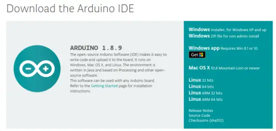
If the Arduino IDE is not installed, follow the link and download the installation file for the operating system of choice.
For Windows users, double click on the downloaded .exe file and follow the instructions in the installation window.
For Linux users, download a file with the extension .tar.xz, which has to be extracted. When it is extracted, go to the extracted directory and open the terminal in that directory. Two.sh scripts have to be executed, the first called arduino-linux-setup.sh and the second called install.sh.
To run the first script in the terminal, open the terminal in the extracted directory and run the following command: she arduino-linux-setup.sh username
username – is the name of a superuser in the Linux operating system. A password for the superuser has to be entered when the command is started. Wait for a few minutes for the script to complete everything.
The second script, called install.sh, has to be used after the installation of the first script. Run the following command in the terminal (extracted directory): sh install.sh
After the installation of these scripts, go to the All Apps, where the Arduino IDE is installed.

Almost all operating systems come with a text editor preinstalled (for example, Windows comes with Notepad, Linux Ubuntu comes with Gedi, Linux Raspbian comes with Leaf pad, etc.). All of these text editors are perfectly fine for the purpose of the eBook.
Next thing is to check if your PC can detect an Arduino board. Open freshly installed Arduino IDE, and go to: Tools > Board > {your board name here} {your board name here} should be the Arduino/Genuine Uno, as it can be seen on the following image:

The port to which the Arduino board is connected has to be selected. Go to: Tools > Port > {port name goes here} and when the Arduino board is connected to the USB port, the port name can be seen in the drop-down menu on the previous image.
If the Arduino IDE is used on Windows, port names are as follows:

For Linux users, for example port name is /dev/ttyUSBx, where x represents integer number between 0 and 9.
How to set-up the Raspberry Pi and Python
For the Raspberry Pi, first the operating system has to be installed, then everything has to be set-up so that it can be used in the Headless mode.
The Headless mode enables remote connection to the Raspberry Pi, without the need for a PC screen Monitor, mouse or keyboard. The only things that are used in this mode are the Raspberry Pi itself, power supply and internet connection. All of this is explained minutely in the free eBook:
Raspberry Pi Quick Startup Guide
The Raspbian operating system comes with Python preinstalled.
Connecting the module with Microcontroller Compatible with Arduino
Connect the DS3231 RTC module with the Microcontroller compatible with Arduino as shown on the following connection diagram:

| Module pin | MC pin | Wire color |
| SCL | A5 | Green wire |
| SDA | A4 | Blue wire |
| VCC | 3.3V | Red wire |
| GND | GND | Black wire |
Library for Arduino IDE
To use the module with a Uno, it is recommended to download an external library. The library we are going to use is called the Reclimb. The version of the library that is used is 1.3.3. To download and install it, open Arduino IDE and go to:
Tools > Manage Libraries.
When new window opens, type Reclimb in the search box and install the library Reclimb made by Adafruit, as shown in the following image:

With the library comes several sketch examples, to open one, go to: File > Examples > Reclimb > ds3231
With this sketch example the module can be tested. The sketch in this eBook is modified version of this sketch, to get more user-friendly output.
Sketch example


Upload the sketch to the Uno and open Serial Monitor: (Tools > Serial Monitor).
The result should look like the output on the following image:

At the beginning of the sketch two libraries called Wire and Reclimb are imported. These libraries are used to import functions that can be used for communication between the module and Uno.
Next, an object called RTC_DS3231 is created with the following line of code: RTC_DS3231 rtc;
Where rtc object represents the RTC module.
Then a char array called days Of The Week is created which represents the names of weekdays, and these predefined names are used to display current day status in the Serial Monitor.
At the beginning of setup() function, communication is started between Uno and RTC with the following line of code: Racebend();
Next, the function called stardust() is used. This function sets date and time in the module. It has one argument, a Date Time object. To set the current date and time of the PC during upload time, the following line of code is used:
stardust(Date Time(F(__DATE__), F(__TIME__)));
When a specific time and date has to be set, it can be done with adjust() and Date Time() functions. For example, if date is to be set to: 09th March 2020. And time to 10:00:00, following line of code can be used: stardust(Date Time(2020, 3, 09, 10, 00, 0));
The Date Time() function has six arguments and returns a Date Time object. The arguments are integer numbers, which represent date and time, in the following sequence: year, day, month, hour, minute and second. The return value is a Date Time object required for setting the date and time in the module.
At the beginning of the loop() function, the data is read from the module and information is stored in the object called now with following line of code: Date Time now = rtc.now();
The object now is type of Date Time. After reading and storing data to this object, properties of this object are called to display data.
The following is the algorithm for displaying the data.
First, day of the week is printed. Next, the current time. The original sketch output displayed values without a leading zero, so a simple if and else statements are added for better output. Each time when numerical values are less than 10, a leading zero is added to the output.
Connecting the module with Raspberry Pi
Connect the DS3231 RTC module with the Raspberry Pi as shown on the following connection diagram:

| RTC pin | Microcontroller pin | Physical pin | Wire color |
| VCC | 3V3 | 1 | Red wire |
| SDA | GPIO2 | 3 | Blue wire |
| GND | GND | 6 | Black wire |
| SCL | GPIO3 | 5 | Green wire |
Enabling the I2C interface
In order to use the module with Raspberry Pi, I2C interface of the Raspberry Pi has to be enabled. Open following menu: Application Menu > Preferences > Raspberry Pi Configuration
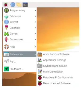
In the new window, under the tab Interfaces, enable the I2C radio button, as on the following image:

To detect I2C address of the module, i2ctools should be installed. If It is not installed, open the terminal and execute the following command:
sudo apt-get install i2ctools -y
Checking the RTC module I2C address is done by executing the following command in the terminal:
i2cdetect -y 1
The output should look like on the following image:
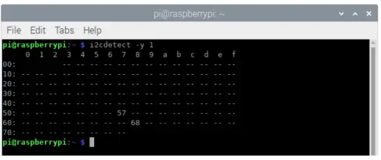
Where, the 0x68 is the I2C address of the RTC module and 0x57 is the I2C address of the EEPROM chip.
If I2C interface is not enabled before executing the previous command, the error will be displayed as on the following image:

Libraries and tools for Python
To use this script, the git app and python-embus library have to be installed. To do so, run the following commands in the terminal: sudor apt-get update sudor apt-get install -y python-embus git
External library script can be downloaded with following command: git clone https://github.com/Slaveche90/az-delivery-ds3231.git
After downloading the library, the script rtc_lib.py can be found in the following directory: /home/pi/az-delivery-ds3231
To change the directory, enter the following command: cd az-delivery-ds3231
Python script
The following is the script for controlling the RTC module:
import time
import rtc_lib # importing library functions
degreasing = u’\xb0′
ds3231 = rtc_lib.SDL_DS3231(1, 0x68)
ds3231.write_now() # saves the current date and time of R. Pi
# ds3231.write_all(seconds=None, minutes=None, hours=None,
day=None, date=None, month=None, year=None, save_as_24h=True)
# Range: seconds [0-59]; minutes [0-59]; hours [0-23]; day [1-7];
# date [1-31]; month [1-12]; year [0-99]
def check(num):
”’A function that put leading zero to single digit number
return: string
”’
if num < 10:
return ‘0{}’.format(num)
else:
return str(num)
print(‘[Press CTRL + C to end the script!]’)
try:
while True:
print(‘\nSystem time: {}’.format(
time.strftime(‘%Y-%m-%d %H:%M:%S’)))
data = ds3231.read_datetime() # return tuple
print(‘RTC date: {} {}.{}.{}’.format(data[0],
data[1], check(data[2]), check(data[3])))
print(‘RTC time: {}:{}:{}’.format(check(data[4]),
check(data[5]), check(data[6])))
# return string
print(‘RTC date time: {}’.format(ds3231.read_str()))
print(‘Temperature: {:.1f}C’.format(ds3231.getTemp(),
degreasing))
time. Sleep(1)
except Keyboard Interrupt:
print(‘\script end!’)
Save the script by the name rtc.py in the same directory where the rtc_lib.py script is saved. To run the script, open the terminal in the directory where the script is saved and run the following command: python3 rtc.py
The result should look like as on the following image:

To stop the script press ‘CTRL + C’ on the keyboard.
The script starts with importing two libraries, time and rtc_lib.
Next, the variable called degreasing is created. The value of this variable represents the UTF8 symbol for degree sign.
Then, the object called ds3231 is created with the following line of code: ds3231 = rtc_lib.SDL-DS3231(1, 0x68)
Where the number 0x68 represents the I2C address of the RTC module.
After this, the date and time in RTC is updated with the following line of code: ds3231.write_now()
The function write now() stores in the RTC module the current date and time of the Raspbian operating system.
There is another option to store time and date data. It can be done with the following line of code:
ds3231.write_all(seconds=None, minutes=None, hours=None, day=None, date=None, month=None, year=None,save_as_24h=True)
The function called write all() has eight arguments and returns no value. The arguments represent part of data for date and time. The values for all arguments are integer numbers in the ranges:
Seconds: 0 – 59, Minutes: 0 – 59, Hours: 0 – 23 Day: 1 – 7 (day in week),
Date: 1 – 31, Month: 1 12, Year: 0 – 99
Save_as_24h: True/False (tested with only as True)
Next, a new function is created, called check(). The function has one argument and returns a string value. It is used to add leading zero to the single digit number. The argument represents the number which is then checked if it is a single or double digit number. If the number is a single digit, then the string value ‘0{}’.format(num) is returned. If the number is not a double digit number then the string value str(num) is returned.
After that, the try-except block of code is created. In the try block of code, the indefinite loop is created. In the indefinite loop the RTC data is read, and displayed in the terminal. There are two ways to display data in the terminal. The first is by using the function read_datetime() and the second is by using the function roadster().
To stop the script press ‘CTRL + C’ on the keyboard. This is called the keyboard interrupt. When the keyboard interrupt happens, the except block of code is executed, displaying message Script end! in the terminal.
The function read_datetime() has two arguments and returns a tuple.
The first argument represents the century, an integer value, for example: for 21st century, use century=21. The second argument represents time zone info, used for datetime objects (it is not covered in this eBook). The return value is a tuple which has seven elements. The elements are: Dayo Week, Dayo Month, month, year, hour, minute and second (in this order). All values for these elements are integer numbers, except the value of Dayo Week argument which is a string value, which represents the name
of the weekday.
The function roadster() has one argument and returns a string value. The argument is the century argument, and is used as the century argument of the read_datetime() function. The return value is a string value, with predefined format for date and time data, as shown in the following script output:
System time: 2020-03-15 15:44:15
RTC date: Sunday 15.03.2020
RTC time: 15:44:15
RTC date time: Sunday 15-03-2020 15:44:15
Temperature: 28.8°C
To get temperature data from the RTC module, use the function called destem(). The function has no arguments and returns a float value. The return value, a float value, represents the temperature data in Celsius.
Now it is the time to learn and make your own projects. You can do that with the help of many example scripts and other tutorials, which can be found on the Internet.
If you are looking for the high quality products for Arduino and Raspberry Pi, AZ-Delivery Vertriebs GmbH is the right company to get them from. You will be provided with numerous application examples, full installation guides, eBooks, libraries and assistance from our technical experts.
https://az-delivery.de
Have Fun!
Impressum
https://az-delivery.de/pages/about-us
Documents / Resources
 |
AZ-Delivery DS3231 Real Time Clock Module [pdf] Instruction Manual DS3231 Real Time Clock Module, DS3231, Real Time Clock Module, Time Clock Module, Clock Module, Module |