![]() DM6000AR
DM6000AR
DIGITAL MULTIMETER
USER MANUAL
INTRODUCTION
Thank you for purchasing the AstroAl True RMS 6000 Counts Digital Multimeter.
This multimeter is designed to be safely and accurately used by professionals in a commercial setting or DIYers who need a little more utility than a standard digital multimeter.
This manual provides all safety information, operation instructions, specifications and maintenance procedures for the meter. The instrument performs AC/DC Voltage, AC/DC Current, Resistance.
Audible Continuity, Diode, hFE. Frequency, Capacitance, and Temperature Testing
Thank you again for choosing AstroAl, if you have any questions or concerns regarding your product, please contact us at support@astroai.com
![]() Fully read and understand this manual before using this Digital Multimeter.
Fully read and understand this manual before using this Digital Multimeter.
![]() WARNING
WARNING
To avoid possible electric shock or personal injury, and to avoid damaging the multimeter or equipment being tested, adhere to the following rules:
- Before using the meer, inspect the exterior casing. Do not use the meter if it is damaged or if any part of the exterior casing is removed. Look for cracks or missing plastic. Pay special attention tothe insulation around its connectors.
- Inspect the test leads for damaged insulation or exposed metal. Check the test leads for continuity
- Do not apply more than the rated voltage, as marked on the meter, between the terminals or between any terminal and grounding.
- The manual rotary switch should be placed in the correct position before any measurements and should NOT be moved during measurements to prevent damage to the meter.
- Wnen the meter is working at an effective voltage over 60V in DC or 30V rms in AC, special care should be taken because there s an increased danger of electric shock.
- Use the appropriate terminals, function and range for your measurements.
- Do not use or store the meter in a high-temperature environment, do not expose to high levels of humidity or se near strong magnetic fields. The performance of the meter may deteriorate after being exposed to any of these environments.
- Disconnect the circuit’s power and discharge all high-voltage capacitors before testing resistance, continuity, diodes or hFE.
- When using the test leads, keep your fingers behind the finger guards.
- Replace the battery as soon as the battery indicator appears. With a low battery, the meter may produce inaccurate readings that can lead to electric shock and personal injury.
- Remove the connection between the testing leads and the circuit being tested, and power off the meter before opening its case.
- When servicing the meter, only use replacement parts with an identical model number or electrical specifications,
- Do not alter the meter’s internal circuit. Doing so may damage the meter.
- Only clean the surface of the meter using a soft cloth and mild soap. Do not use abrasive materials or harsh chemicals, doing s0 may corrode and damage the meter.
- Turn the meter off when not in use and take out the battery when itis not going to be used for an extended period of time. Regularly check the battery as it may leak when it has not been used for some time. Replace the battery as soon as leakage appears. A leaking battery will damage the meter.
INCLUDED IN BOX
| User Manual | x1 |
| Pair of Test Leads | x1 |
| K-Type Thermocouple | x 1 |
| Multi-Function Socket | x 1 |
| AstroAl 6000 Counts Multimeter | x1 |
ACCESSORIES
Magnetic Hanger
The Magnetic Hanger can be used to hang the product and free your hands to operate it. When in use, keep the magnetic hanger perpendicular to the multimeter to better secure it.
Pair of Test Leads
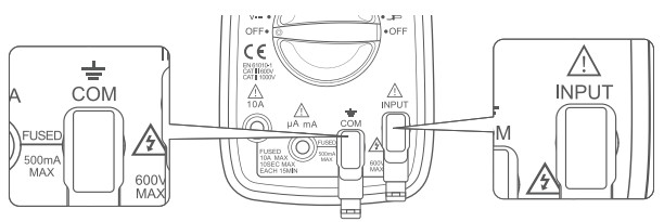
Insert the red test lead into the “Input” jack and the black test lead into the “COM” jack. The test leads are used In a variety of tests, please connect them as instructed.
K-Type Thermocouple
When measuring the temperature, insert the red test lead into the “Input” jack and the black test lead into the “COM” Jack.
Note: The leads must not be connected in reverse.
Multi-Function Socket
Use the multi-function socket to measure both capacitors and transistors.
Be sure to correctly insert the multi-function socket into the COM and INPUT jacks. The negative terminal is on the left side of the multi-function socket and the positive terminal is on the right side.
Note: The leads must not be connected in reverse.
| Duty Cycle | |
| Fahrenheit Temperature | |
| Celsius Temperature | |
| Transistor hFE | |
| Continuity Test | |
| Diode Test | |
| Resistance | |
| External Current Test (Clamp) | |
| Capacitance | |
| Relative Mode | |
| Earth Ground | |
| Double Insulated | |
| Warning | |
| Dangerous Voltage may be pres | |
| APO | Automatic Power-Off |
| H | Data Hold |
| MAX | Maximum Reading |
| MIN | Minimum Reading |
| DC (Direct Current) | |
| AC (Alternating Current) | |
| – | Negative Reading |
| AC and DC | |
| Hz | Frequency |
| AUTO | Auto-range Mode |
| Low Battery | |
| Fuse | |
| Complies with EU directives |
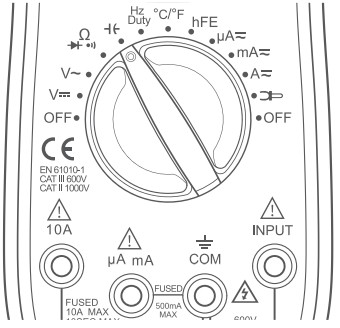
DIAGRAM

| (1) Magnetic Hanger | (6) Rotary Function Switch |
| (2) LCD Screen | (7) INPUT Terminal |
| (3) Function Buttons | (8)COM Terminal |
| (4) 10 A Terminal | (9) Silicone Sleeve |
| (5) µA/mA Terminal |
 (10) Pair of Test Leads
(11) Multi-Function Socket
(12) K-Type Thermocouple
Select Button
When using the rotary switch to select a multimeter function, use the Select Button to select a more specific function. This applies only to multifunction settings like the temperature, test functions, AC power and DC power.
Hold and Backlight Function Button
a. When taking a measurement, press this button to hold the data for easier recording. Press the button again to remove the hold function.
b. Press and hold this button to turn on the backlight on the LCD screen.
Press again to turn off the backlight.
Max/Min Button
When taking a measurement, press this button once to enter “Max Mode”.
In this mode, the multimeter will capture the highest reading it records.
Press this button again to enter “Min Mode” which will capture the lowest reading it records.
Press and hold this button to exit the Max/Min Modes.
Range Button
AC/DC Voltage, AC Current, and Resistance can all be measured in both Auto and Manual ranging. The multimeter will ship set to Auto. To manually select the range, press the Range Button repeatedly to find the desired range. Beware of selecting a range too low, as it will overload the device and the multimeter will not give a reading.
Press and hold the Range Button to return to Auto Ranging.
Relative Button
When taking measurements, the Relative Button can be used to get more accurate readings by removing the resistance of the test leads, for example. To activate this function, simply press the Relative Button. A small triangle (delta symbol) will appear on the display and the reading should change to zero.
Press the Relative Button again to exit relative mode.
Hz/Duty Button
When using the “Hz Duty” function on the multimeter, quickly switch functions by pressing this button.
PREPARATION
Continuity Test
a. Turn the rotary dial to the “ ![]() ” setting, choose the “Select” button and select Continuity Mode, the “
” setting, choose the “Select” button and select Continuity Mode, the “ ![]() ” symbol will display on the screen.
” symbol will display on the screen.
b. Touch the red and black test leads together to ensure they’re working normally. The buzzer will beep if the test leads are functioning normally.
OPERATING INSTRUCTIONS
I. Voltage Measurement
- Connect the test leads: Insert the red test lead into the “Input” jack and the black test lead into the “COM” jack.

- Choose functions: Choose functions: Turn the rotary switch to the “
 ” or “
 ” setting according to the measured voltage.
 - Connect the circuit: Connect one end of the test leads to the circuit that needs to be measured, in parallel with the circuit.

- Reading: record the reading from the LCD screen.
- After measuring, turn the rotary switch to the OFF position to turn off the meter.
NOTE:
- When a small measuring range is selected, the display of the multimeter may show unstable results if the test leads are not connected to the load. This is a normal event and will not affect the measurements.
- During DC voltage measurements, use the “ -” symbol on the screen to judge the polarity of the red test lead connection. Without the “- ” symbol onscreen, the red test lead is connected with positive polarity.
- To avoid damaging the meter, do not measure voltages exceeding 600 V DC or 600 V AC.
- If necessary, the “Range” Button can be pressed to manually set the range (default mode is auto range). During manual operation, please choose the widest range by pressing the “Range” Button, then choose an appropriate range based on the initial readings. When the “OL” symbol is displayed on the screen, users must choose a wider range to obtain a reading. In Auto Range Mode, a range does not need to be manually set.
- Do not use the AC voltage test function to test DC voltage and vice versa.
Performing this action has the potential to damage the meter or any components you are attempting to test.
ll. Current Measurement
- If the current to be measured is less than 600 mA, insert the red test lead into the “yA” “mA’ jack. If the current is between 600 mA and 10 A, insert the red test lead into the “10 A’ jack instead.

- Choose functions: Turn the rotary switch to the “µA”, “mA‘ or “A’ setting according to the estimated value.

- Choose current types: Press the “Select” Button to choose between a DC or AC current test.

- Connect the circuit: Connect the test lead to the source lead or load to be measured in series with the circuit.
- Reading: record the reading from the LCD screen.
- After measurement, turn the rotary switch to the OFF position to turn off the meter.
NOTE:
- DO NOT test currents exceeding 10 A AC/DC.
- When performing DC current measurements, determine the polarity of the red lead connection based on the presence or absence of ” – “on the display.
- For your safety when testing a high current, each measurement time should be less than 10 seconds, and the interval time between tests should be greater than 15 minutes.
- When testing the current, there must be a load in the circuit. Do not connect the multimeter in series with the circuit without a load to measure; doing so may damage the meter.
- If necessary, the “Range” Button can be pressed to operate manually (default mode is auto range). During manual operation please choose the widest range by pressing the “Range” Button, then set an appropriate range based on the initial reading access to precise reading. When the “OL’ symbol is displayed on the screen, set a wider range to get results. In Auto Range Mode, a range does not need to be manually set.
Ill. Current Measurement (with Clamp Attachment)
- Connect the leads: use clamps to test AC current. Insert the black test lead into the “COM” jack, if the current is less than 600 mA, insert the red test lead into the “µA” “mA” Jack. If the current ranges from 600 mA to 10 A, please insert the red test lead into the “10A” jack.

- Choose functions: Turn the rotary switch to the “
 ” setting.
- Then, clamp the circuit to be tested and slowly release the trigger until the clamp head Is completely closed. Ensure the circuit to be tested is in the center of the clamp head.
- Reading: record the reading from the LCD screen.
- After completing your measurement, turn the rotary switch to the OFF position to turn off the meter.
NOTE:
- Each time a measurement is taken, ensure only one cable is clamped and Is in the center of the clamp jaws.
- The clamp can only test up to 600 A, do not test circuits higher than 600 A.
- Do not touch the circuit with your hand or skin.
- The multimeter assumes a clamp has a sensitivity of 1 A/1 mV. The indicated value is the same as the measured value for clamps with 1 A/1 mv.
- lf you use a clamp with a sensitivity that does not equal 1 mV/1 A, multiply the present reading by a factor that is determined by the used clamp, the result is the measured value. To determine this factor, please refer to the instruction manual of the other clamp.
IV . Resistance Measurement
- Connect: Insert the black test lead into the “COM” jack and the red test lead into the “INPUT” jack.
- Choose functions: Turn the rotary switch to the
 setting, the “M
 “symbol will display on the screen.
- Connect load: Place the test leads at both ends of the load to be measured.
- Reading: record the reading from the LCD screen.
- After measurement, turn the rotary switch to the OFF position to turn off the meter.
NOTE:
- If the resistance test value exceeds 1 MΩ, the meter may take a few seconds to stabilize the reading, which is normal for high resistance testing.
- Do not change the resistance while taking measurements. Doing so may damage the meter and affect the test results.
- Do not test parallel circuits. The accuracy of the measurement will be affected, and the results may not be accurate.
- Do not directly measure the internal resistance of micrometers, galvanometers, batteries and other such instruments.
- In case of disconnection, the symbol “OL” will be displayed.
- Before testing the internal resistance of the circuit, please ensure that all power sources are removed from the tested circuit and all capacitors are fully discharged.
- If necessary, the “Range” Button can be pressed to operate manually (default mode is auto range). During manual operation please choose the widest range by pressing the “Range” Button, then set an appropriate range based on the initial reading access to precise reading. When the “OL” symbol is displayed on the screen, set a wider range to get results. In Auto Range Mode, a range does not need to be manually set.
V . Continuity Test
- Connect: Insert the black test lead into the “COM” jack and red test lead into the “INPUT” jack.

- Turn the rotary switch to the “ “setting, choose the “Select” Button.
- Then, select continuity Mode, the “
 ” symbol will display on the screen.
 - Touch the red and black test leads together to check whether they are functioning normally. The buzzer will beep if the test leads are working correctly.

- Connect load: Place the test leads at both ends of the resistance or load to be measured.
- Reading: If the circuit load is less than 30 , the buzzer will buzz. If it exceeds 30 , the LCD screen will display the load reading.
- After measurement, turn the rotary switch to the OFF position to turn off the meter.
VI . Diode Test
- Connect: Insert the black test lead into the “COM” jack and the red test lead into the “INPUT” jack.

- Operation: Turn the rotary switch to the “” setting and choose the “Select” Button. Then, choose diode test mode, the “
 ” symbol will display on the LCD screen.
- Connect diode: Connect the red test lead to the positive end of the diode and the black test lead to the negative end,
- Reading: The meter will display the approximate value of positive voltage. If the leads are incorrectly connected to the diode electrodes, the LCD will display “OL” To fix this change the test leads position.
- After measurement, turn the rotary switch to the OFF position to turn off the meter.
NOTE:
- Is the diode functioning correctly? If the red test lead is connected to the po sitive pole of the diode and the black lead is connected to negaive, then the diode should be in a forward conduction state, and the displayed value is the forward voltage drop.
- Normal diode forward pressure drop: the general silicon tube is 05-0.7 Ω, germanium tube is 0.15-0.3V.
- Polarity Judgment Method:
1 Switch the multimeter to the Resistance setting.
2 Connect the two test leads to the two electrodes of the diode.
3 Measure one result, then swap the positions of the test leads, then measure the second result
4 The larger result is the reverse resistance and the smaller result is the forward resistance. The smaller resistance is when the black test lead is connected to the positive end of the diode and the red lead is connected to the negative end.
VII. Transistor Test
- Connect Multi-Function Socket: Connect Multi-Function Socket with the meter, plug the negative terminal into the “COM” jack and the positive terminal into the “INPUT jack

- Choose functions: choose the “hFE” setting.

- Measurement of Transistor: Identify whether the transistor is an NPN or PNP type, and identify emitter, base and collector terminals. Insert the terminals into the adapter transistor test socket.
- Reading: record the hFE value on the LCD screen.
- After measurement, turn the rotary switch to the OFF position to turn off the meter.
NOTE:
- The connection between the meter and Multi-Function Socket is vital please connect them as instructed, or a false reading will display on the LCD screen.
VIl . Temperature Measurement
- Insert the negative (-) plug of the K-type thermocouple into the “COM” jack and the positive (+) plug into the “INPUT jack

- Turn the rotary switch to the “°C/°F” setting.

- Choose units: Press the “Select” Button to switch from °C or °F.
- Method: Carefully touch the end of the K-Type thermocouple to the object being measured
- Reading: Record the stable result on the LCD screen,
- After the measurement, turn the rotary switch to the OFF position to turn off the meter,
IX . Capacitance Measurement
- Connect test leads: Insert the black test lead into the “COM” jack and the red test lead into the “INPUT” jack.

- Choose functions: Turn the rotary switch to the “
 ” setting.
- Connect Capacitance: Connect Capacitance, insert the red test lead into the positive pole and the black test lead into the negative pole.
- Reading: record the reading from the LCD screen.
- After measurement, turn the rotary switch to the OFF position to turn off the meter.
X. Test Method for Long Capacitance Terminals
- Connect the Multi-Function Socket: Connect the Multi-Function Socket with the meter, plug the negative terminal into the “COM” jack and the positive terminal into the “INPUT” jack.

- Choose functions: Turn the rotary switch to the “” setting.
- Connect Capacitance: Insert the Capacitance postive pole into the INPUT” jack of the Multi-Function Sacket and the negative pole into the ‘COM” jack of the Multi-Function Sacket.
- Reading: record the reading from the LCD screen
- After measurement,turn the rotary switch to the OFF position to turn off the Meter.
NOTE:
- When the capacitance being measured is more than 600 uF, it needs at least 10 seconds for the readings to stabilize.
- The connection between the meter and Multi-Function Socket is vital. please connect them as instructed, or a false reading will display on the LCD screen
- The connection between the positive and negative terminals of the capacitor and the test leads or Multi-Function Socket must operate as per the instructions, or the wrong value will be displayed.
XI . Frequency Measurement
- Connect test leads: Insert the black test lead into the “COM” jack and the red test lead into the ‘INPUT” jack.

- Choase functions: Turn the rotary switch to the “Hz/Duty” setting. Press the “Hz/Duty” Button to switch frequency measurement or duty ratio measurement

- Connect signal source: Connect the test leads to the two ends of the circuit to be measured.
- Reading: record the reading from the LCD screen
- After measurement, turn the rotary switch to the OFF position to turn off the Meter.
MAINTENANCE
Battery Replacement
If the “![]() * symbol appears on the display, the battery should be replaced immediately.
* symbol appears on the display, the battery should be replaced immediately.
- Turn off the power and remove the test leads plugged into the meter.
- Open the kickstand, unscrew the screws and remove the kickstand to replace the battery.
- Replace with a NEDA 1604, 6F22, or equivalent 9V battery.
- Put the kickstand in place and fasten it with screws.

Fuse Replacement
Fuses will rarely need replacement and are normally only blown due to operator error.
- Turn off the power and remove the test leads plugged into the meter.
- Open the kickstand, unscrew the screws and remove the kickstand to replace the fuse.
- Remove the blown fuses and replace them with new fuses of the same specification.
- Put the kickstand in place and fasten it with screws.

NOTE:
Replace the damaged fuse with a new one with the same ratings. This meter uses two fuses:
- Fuse 1:500 mA, 600V, φ6 x 30 mm
- Fuse 2:10A, 600V, φ6 x 30 mm
SPECIFICATIONS
| Digital Display | 3 5/6,5999 |
| Sampling Speed | 2Times Per Second |
| LCD Size | 6442 mm/252×1 65 in |
| Range Selection | Auto and Manual |
| Polarity Indication | Yes |
| Overload Indication | Yes |
| Low Battery Indication | Yes |
| Operating Environment | 32°F ~ 104 °F (0 °C ~ 40 °C); <80% RH |
| Storage Temperature | 14 °F ~ 122 °F (10 °C ~ 50 °C); <85% RH |
| Power | 1X9V6F22 Battery Included |
| Dimensions | 7.48 % 339 x 157 in/190 x 86 x 40 mm |
| Weight | Approx0.71 bs/320 g |
| Safety/Compliances | EN 61010-1 CAT Il 600, CATII 1000V |
DETAILED SPECIFICATIONS
- Accuracy is guaranteed for 1 year 73 °F ± 9 °F/23 °C ± 5 °C less than 80%RH
I. DC Voltage (Auto ranging)
| Range | Resolution | Accuracy |
| 600 MV, | 0.1 mV | ±(08% + 5) |
| 6V | 1V | ±(08%+3) |
| 60V | 10 mV | |
| 600V | 100 mV. | |
| 1000V | 1V | ±(1.0%+5) |
- Input Impedance: 10 M
- Overload Protection: 600V DC/AC RMS
- Max Input Voltage: 600 V DC
- Measure DCV 1000 V under CATII
ll AC Voltage (Auto ranging)
| Range | Resolution | Accuracy |
| 600 MV, | 0.1 mV | ±(1.2% + 8) |
| 6V | 1V | ±(1.2%+6) |
| 60V | 10 mV | |
| 600V | 100 mV. | |
| 1000V | 1V | ±(1.2% + 8) |
- Input Impedance: 10 M
- Frequency Range: 40 Hz~400 Hz
- Overload Protection: 600 V DC/AC RMS
- Measure ACV 750V under CATII CAT lll
- MaxInput voltage: 400V AC RMS CAT lll
III Temperature
| Range | Resolution | Accuracy |
| -40°C~1370°C | 1°C | -40°C =150 °C: ± (1% + 4) |
| -40°F~302°F | 1°F | ±(5%+4) |
| 302°F~2000°F | ±(2.5%+3) |
Overload Protection: F0.5 A/600 V Fuse
IV.DC Current
| Range | Resolution | Accuracy |
| 600 yA | 0.1 pA | ±(0.8%+5) |
| 6000 pA | 1ypA | |
| 60 mA | 10 yA | |
| 600 mA | 100 pA | |
| 6A | 1 mA | ±(1.5%+3) |
| 10A | 10 mA |
Overload Protection:
- “mA” Jack: F0.5 A/600 V fuse
- “10A” Jack: F10 A/600 V fuse
Max Input Current:
- “mA” Jack: 500 mA
- “10A” Jack: 10 A
(For measurements >5 A: Duration <10 seconds, interval >15 minutes)
Voltage Drop:
- 600 μΑ. 60 mA: 60 mV
- 6000 μΑ, 600 mA and 10A ranges: 600 mV
V. Transistor hFE Test (Connect Adapter)
| Range | hFE | Test Current | Test Voltage |
| PNP & NPN | 0~1000 | Ib |
Vee |
Vi. AC Current
| Range | Range | Accuracy |
| 600 µA | 600 µA | ±(1.5%+8) |
| 6000 µA | 6000 µA | |
| 60 mA | 60 mA | |
| 600 mA | 600 mA | |
| 6A | 6A | ±(2.0%+10) |
| 10A | 10A |
Overload Protection:
- “mA” Jack: F0.5 A/600 V fuse
- “10A” Jack: F10 A/600 V fuse
Max Input Current:
- “MA’ Jack: 500 mA
- “10A” Jack: 10A
For measurements>5 A: duration<10 seconds, interval >15 minutes)
Voltage Drop:
- 600 µA, 60 mA ranges: 60 mV
- 6000 µA, 600 mA and 10 A ranges: 600 mV
- Frequency Range: 40 Hz ~ 400 Hz
VII. Resistance (Auto Ranging)
| Range | Resolution | Accuracy |
| 600 |
0.1 |
±(1.5%+3) |
| 6K |
1 |
|
| 60 K |
10 |
|
| 600 K |
100 |
|
| 6 M |
1k |
|
| 60 M |
10 K |
±(2.0%+5) |
- Open Circuit Voltage: About 0.25 V
- Overload Protection: 250 VDC/AC RMS
VIII. 600 A AC current through a clamp (DT3303 optional)
| 600 A | 1mV/10A | ±(2.5%+10) |
| 200A | 1mv/1A |
IX . Diode and Continuity
| Range | Introduction | Remark |
| The approximate forward voltage drop will be displayed | Open circuit voltage: about 1.5V | |
| The built-in buzzer will sound if the resistance is less than about 30 0 | Open circuit voltage: about 0.5 V |
Overload Protection: 250 V DC/AC RMS
| Range | Resolution | Remark |
| 60 nF | 10 pF | ±(8%+5) |
| 600 nF | 100 pF | |
| 6 uF | 1nF | |
| 60 uF | 10 nF | |
| 600 uF | 100 nF | |
| 6 mF | 1 uF | |
| 20 mF | 10 uF |
- Overload Protection: F0.5 A/600 V fuse
- Open Circuit Voltage: About 0.5 V
XI. Frequency (Auto Ranging)
| Range | Accuracy |
| 10 Hz~10 MHz | ±(1.0%+5) |
Overload Protection: 250 V DC/AC RMS
RECYCLING
You may dispose of the product when its service life has ended, please recycle the recyclable parts according to local guidelines.
WARRANTY PERIOD
3-YEAR LIMITED WARRANTY FROM ASTROAI
Each AstroAl Digital Multimeter will be free from defects in material and workmanship.
This warranty does not cover fuses, disposable batteries and damage from neglect, misuse, contamination, alteration, accident, or abnormal conditions of operation or handling, including overvoltage failures caused by use outside the Multimeter’s specified rating, or normal wear and tear of mechanical components.
This warranty covers the original purchaser only and is not transferable.
If this product is defective, please contact AstroAl Customer Support at support@astroai.com
![]() Web: www.astroai.com
Web: www.astroai.com
E-Mail: support@astroai.com
V2.4
Documents / Resources
 |
ASTROAI DM6000AR Digital Multimeter [pdf] User Manual DM6000AR, DM6000AR Digital Multimeter, Digital Multimeter, Multimeter |