
1. Introduction
The UNITY MAS830L Digital Multimeter is a portable, battery-powered instrument designed for accurate electrical measurements. It is suitable for a wide range of applications, including testing AC/DC voltage, DC current, resistance, diode, and transistor hFE. Its backlit LCD display ensures clear readings in various lighting conditions, making it a versatile tool for professionals and hobbyists alike.
2. Safety Information
To ensure safe operation and to avoid damage to the meter, please read and follow all safety instructions carefully. Failure to observe these warnings can result in electric shock, injury, or damage to the meter or equipment under test.
- Always ensure the meter is in good working condition before use. Do not use if the meter or test leads appear damaged.
- Do not apply more than the rated voltage, as marked on the meter, between terminals or between any terminal and earth ground. The maximum operating voltage is 600V.
- Use extreme caution when working with voltages above 60V DC or 30V AC RMS. These voltages pose a shock hazard.
- Always disconnect the test leads from the circuit before changing functions or ranges.
- Be careful when making measurements on circuits with high current. Ensure the correct input jack and range are selected.
- Replace the battery when the low battery indicator appears to ensure accurate readings.
- Do not operate the meter in explosive gas, vapor, or dust environments.
- Keep fingers behind the finger guards on the test probes during measurements.
3. Package Contents
Verify that all items listed below are present in your package:
- UNITY MAS830L Digital Multimeter
- Red Test Lead
- Black Test Lead

Image: The UNITY MAS830L Digital Multimeter shown with its included red and black test leads, as received in the package.
4. Product Overview
The MAS830L features a compact design with a clear backlit LCD display and an intuitive rotary dial for function selection. Key components include:
- LCD Display: Shows measurement readings, units, and indicators.
- Function Rotary Switch: Used to select the desired measurement function and range.
- "H" (Hold) Button: Freezes the current reading on the display.
- Backlight Button: Activates the display backlight for improved visibility.
- Input Jacks:
- "COM" Jack: Common terminal for all measurements (connect black test lead).
- "VΩmA" Jack: Input for voltage, resistance, diode, continuity, and current up to 200mA (connect red test lead).
- "10A" Jack: Input for DC current measurements up to 10A (connect red test lead for high current).
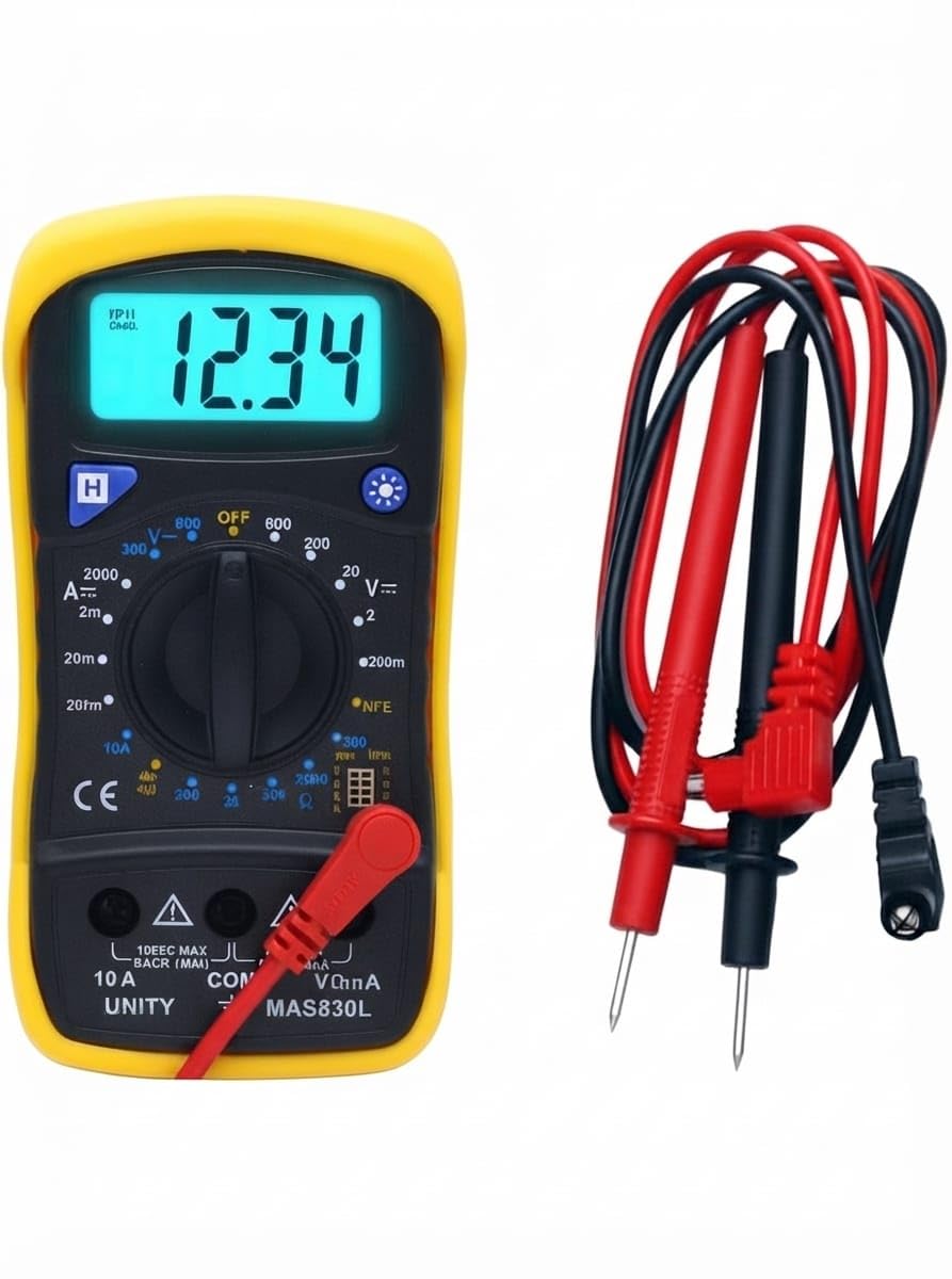
Image: Detailed view of the MAS830L multimeter's front panel, highlighting the LCD, function dial, and input terminals.
5. Setup
5.1. Battery Installation
The MAS830L multimeter typically uses a 9V battery (not always included). To install or replace the battery:
- Ensure the multimeter is turned OFF and test leads are disconnected.
- Locate the battery compartment cover on the back of the meter.
- Unscrew the retaining screw(s) and remove the cover.
- Connect a new 9V battery to the battery clip, observing correct polarity.
- Place the battery into the compartment and replace the cover, securing it with the screw(s).
5.2. Connecting Test Leads
Always connect the black test lead to the "COM" (Common) input jack. Connect the red test lead to the appropriate input jack based on the measurement type:
- For Voltage, Resistance, Diode, Continuity, and current up to 200mA: Connect the red test lead to the VΩmA jack.
- For DC Current measurements up to 10A: Connect the red test lead to the 10A jack.
6. Operating Instructions
Before taking any measurement, ensure the test leads are correctly connected and the function switch is set to the desired range.
6.1. Power On/Off and Backlight
- To turn the meter ON, rotate the function switch from "OFF" to any desired measurement range.
- To turn the meter OFF, rotate the function switch to the "OFF" position.
- Press the backlight button (often marked with a light bulb icon) to illuminate the LCD display. Press again to turn it off.
6.2. DC Voltage Measurement (V=)
- Connect the black test lead to the "COM" jack and the red test lead to the "VΩmA" jack.
- Set the function switch to the desired DC Voltage range (e.g., 20V, 200V, 600V). If the voltage is unknown, start with the highest range and decrease as needed.
- Connect the test probes across the component or circuit to be measured, observing polarity.
- Read the voltage value on the LCD display.
6.3. AC Voltage Measurement (V~)
- Connect the black test lead to the "COM" jack and the red test lead to the "VΩmA" jack.
- Set the function switch to the desired AC Voltage range (e.g., 200V, 600V).
- Connect the test probes across the AC voltage source.
- Read the voltage value on the LCD display.
6.4. DC Current Measurement (A=)
Caution: Never connect the meter in parallel with a voltage source when measuring current, as this can blow the fuse or damage the meter.
- Determine the expected current. For currents up to 200mA, connect the red test lead to the "VΩmA" jack. For currents up to 10A, connect the red test lead to the "10A" jack. Always connect the black test lead to "COM".
- Set the function switch to the appropriate DC Current range (e.g., 200mA, 10A).
- Open the circuit where current is to be measured and connect the meter in series with the load.
- Read the current value on the LCD display.
6.5. Resistance Measurement (Ω)
Caution: Ensure the circuit under test is completely de-energized before measuring resistance. Disconnect power and discharge all capacitors.
- Connect the black test lead to the "COM" jack and the red test lead to the "VΩmA" jack.
- Set the function switch to the desired Resistance range (e.g., 200Ω, 2kΩ, 20kΩ, 200kΩ, 2MΩ).
- Connect the test probes across the resistor or component.
- Read the resistance value on the LCD display.
6.6. Diode Test (→|)
- Connect the black test lead to the "COM" jack and the red test lead to the "VΩmA" jack.
- Set the function switch to the Diode Test position.
- Connect the red probe to the anode and the black probe to the cathode of the diode. The display will show the forward voltage drop (typically 0.5V to 0.8V for silicon diodes).
- Reverse the probes. The display should show "OL" (Open Loop) for a good diode. A reading in both directions or "0" indicates a shorted diode.
6.7. Continuity Test ())))
- Connect the black test lead to the "COM" jack and the red test lead to the "VΩmA" jack.
- Set the function switch to the Continuity Test position.
- Connect the test probes across the circuit or component.
- If the resistance is below a certain threshold (typically <50Ω), the buzzer will sound, indicating continuity. The display will also show the resistance value.
6.8. Transistor hFE Test
The MAS830L includes a socket for testing the DC current gain (hFE) of NPN and PNP transistors.
- Set the function switch to the "hFE" position.
- Identify the Emitter (E), Base (B), and Collector (C) leads of the transistor.
- Insert the transistor leads into the corresponding holes in the hFE test socket, ensuring correct NPN or PNP type selection.
- Read the hFE value on the LCD display.

Image: The MAS830L multimeter in operation, showing a DC voltage reading on its backlit display while connected to a breadboard circuit.
7. Maintenance
7.1. Cleaning
Wipe the meter with a damp cloth and mild detergent. Do not use abrasives or solvents. Ensure the meter is completely dry before use.
7.2. Battery Replacement
When the low battery indicator appears on the display, replace the 9V battery as described in Section 5.1. Remove the battery if the meter is not used for an extended period to prevent leakage.
7.3. Storage
Store the multimeter in a cool, dry place, away from direct sunlight and extreme temperatures. Disconnect test leads and remove the battery if storing for a long duration.
8. Troubleshooting
| Problem | Possible Cause | Solution |
|---|---|---|
| No display or dim display | Dead or low battery; Incorrect battery installation | Replace battery; Check battery polarity |
| "OL" (Overload) displayed | Measurement exceeds selected range; Open circuit (for continuity/resistance) | Select a higher range; Check for breaks in the circuit or component |
| Incorrect readings | Incorrect function/range selected; Poor test lead connection; Damaged test leads; Low battery | Verify function and range; Ensure firm connections; Inspect/replace test leads; Replace battery |
| No continuity beep | Open circuit; Resistance too high | Check circuit for breaks; Ensure resistance is below threshold for beep |
9. Specifications
| Feature | Specification |
|---|---|
| Brand | Generic (UNITY) |
| Model Number | MAS830L |
| Power Source | Battery Powered (9V, not always included) |
| DC Voltage Range | Up to 600V |
| AC Voltage Range | Up to 600V |
| DC Current Range | Up to 10A |
| Resistance Range | Up to 2MΩ |
| Measurement Types | AC Voltage, DC Current, DC Voltage, Diode Test, Resistance, Transistor hFE, Continuity |
| Display | Backlit LCD |
| Data Hold | Yes |
| Item Weight | 200 Grams |
| Item Dimensions | 17 x 7.5 x 3.5 Centimeters |
| Operating Temperature | Up to 40 Degrees Celsius |
| Safety Standard | CE |
10. Warranty and Support
For warranty information and technical support, please refer to the documentation provided with your purchase or contact the retailer/manufacturer directly. Keep your purchase receipt as proof of purchase for any warranty claims.


