
1. Introduction
Thank you for choosing the VIHELM CM88C Digital Clamp Meter. This instrument is a professional, portable measuring device with a large LCD display, backlight, and various functions including AC/DC current, AC/DC voltage, resistance, capacitance, frequency, temperature, diode, continuity, NCV (Non-Contact Voltage), and Live Wire detection. It features True RMS and Auto Range capabilities for accurate and reliable measurements. Please read this manual thoroughly before use to ensure safe and correct operation.
2. Safety Information
WARNING: To avoid electric shock or personal injury, please read and understand all safety information before using this product.
- Always adhere to local and national safety codes.
- Do not use the meter if it appears damaged or if the insulation is compromised.
- Do not apply more than the rated voltage, as marked on the meter, between the terminals or between any terminal and earth ground.
- Use caution when working with voltages above 30V AC RMS, 42V peak, or 60V DC. These voltages pose a shock hazard.
- Always use the correct terminals, function, and range for measurements.
- Ensure the test leads are in good condition and free from cracks or damage.
- Remove the test leads from the circuit before changing functions.
- Replace the battery immediately when the low battery indicator appears.
- Do not operate the meter in explosive gas, vapor, or dusty environments.
3. Product Overview
3.1. Parts List
The VIHELM CM88C Digital Clamp Meter package includes the following components:
- CM88C Digital Clamp Meter x1
- Test Leads x1 pair
- Thermocouple Probe x1
- Storage Bag x1
- User Manual x1
- Batteries (AAA) x2 (may vary by region)
- Screwdriver x1

Figure 3.1: The VIHELM CM88C Digital Clamp Meter shown with its complete set of accessories, including test leads, thermocouple, storage bag, and batteries.
3.2. Key Features
- True RMS Measurement: Provides accurate readings for non-sinusoidal waveforms.
- Auto Range: Automatically selects the appropriate measurement range.
- Large Jaw Design: The clamp jaw opens up to 30mm, allowing for easy clamping around various conductors.
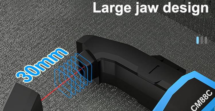
Figure 3.2: A detailed view highlighting the 30mm large jaw design of the CM88C, facilitating measurements on larger conductors.
4. Setup
4.1. Battery Installation
- Ensure the meter is powered off.
- Locate the battery compartment cover on the back of the meter.
- Use a screwdriver to loosen the screw(s) and remove the cover.
- Insert two AAA batteries, observing the correct polarity (+/-).
- Replace the battery compartment cover and secure it with the screw(s).
4.2. Connecting Test Leads
For voltage, resistance, capacitance, diode, and continuity measurements, connect the test leads as follows:
- Insert the red test lead into the "INPUT" terminal.
- Insert the black test lead into the "COM" terminal.
5. Operating Instructions
5.1. AC/DC Voltage Measurement (AUTO-VLOZ)
The CM88C features automatic recognition of AC/DC voltage. The instrument will automatically identify whether the voltage is AC or DC based on the measured voltage signal and display the voltage value.
- Turn the rotary switch to the V~ or V- position, or the AUTO-VLOZ setting.
- Connect the test leads in parallel to the circuit or component to be measured.
- Read the voltage value displayed on the LCD screen.
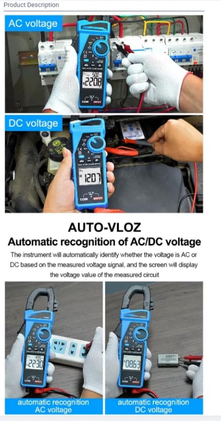
Figure 5.1: Examples of AC voltage measurement in a household circuit and DC voltage measurement on a car battery, demonstrating the meter's automatic recognition feature.
5.2. Frequency Measurement
To measure the frequency of a signal source:
- Turn the rotary switch to the frequency measurement function.
- Connect the test leads to the signal source.
- The screen will display the frequency value and the percentage of the measured signal.
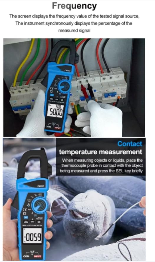
Figure 5.2: The clamp meter displaying a frequency reading while connected to an electrical panel.
5.3. Contact Temperature Measurement
To measure temperature using the thermocouple probe:
- Turn the rotary switch to the temperature function (usually marked with °C/°F).
- Insert the thermocouple probe into the INPUT and COM terminals, observing polarity.
- Place the thermocouple probe in contact with the object or liquid to be measured.
- Press the SEL key briefly if needed to switch between Celsius and Fahrenheit.
- Read the temperature value on the screen.
Figure 5.3: The clamp meter displaying a temperature reading using the included thermocouple probe.
5.4. Non-Contact AC Voltage (NCV) Detection
The NCV function allows for detection of AC voltage without direct contact.
- Turn the rotary switch to the NCV position.
- Bring the NCV sensing area of the instrument close to the circuit or conductor.
- Different alarm prompts (audible and visual) will be sounded according to the voltage intensity, and the screen will display 'L' for low voltage or 'H' for high voltage.
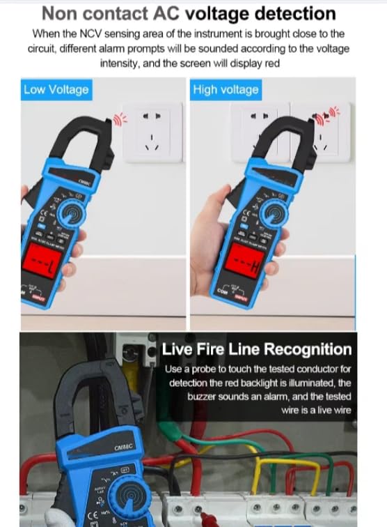
Figure 5.4: The clamp meter indicating low and high AC voltage detection using the NCV feature near electrical outlets.
5.5. Live Fire Line Recognition
This function helps identify live wires.
- Turn the rotary switch to the Live Wire detection function.
- Use a test probe to touch the tested conductor.
- If the red backlight is illuminated and the buzzer sounds an alarm, the tested wire is a live wire.
Figure 5.5: The clamp meter's probe touching a wire, indicating a live wire through visual and audible alerts.
5.6. Surge Current Measurement (Inrush)
To measure the peak current when a machine starts:
- Turn the rotary switch to the AC current mode.
- Press and hold the INRUSH button to activate the surge current measurement function.
- Before measuring, disconnect the load power supply.
- Clamp the meter around the conductor of the load.
- Reconnect the load power supply and observe the peak current reading.
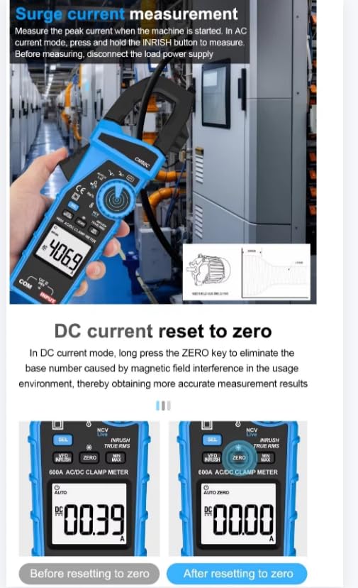
Figure 5.6: The clamp meter displaying a surge current reading during the startup of an industrial machine.
5.7. DC Current Reset to Zero
In DC current mode, a residual reading may sometimes appear due to magnetic field interference. This function allows you to reset the display to zero for more accurate measurements.
- Turn the rotary switch to the DC current mode.
- Ensure the clamp jaw is open and not clamping any conductor.
- Long press the ZERO key.
- The display will reset to 0.00, eliminating any base number caused by magnetic field interference.
Figure 5.7: Comparison of the meter's display showing a non-zero reading before reset and a 0.00 reading after applying the DC current zero function.
5.8. Data Hold Function
The Data Hold function allows you to freeze the current reading on the display.
- While taking a measurement, press the HOLD button.
- The reading on the display will be frozen. The "HOLD" indicator will appear.
- Press the HOLD button again to release the reading and return to live measurement.
- A warning buzzer will sound every 2 seconds to remind you that the display is in a locked state.

Figure 5.8: The clamp meter's display showing a frozen reading with the "HOLD" indicator active.
5.9. Capacitance Measurement
- Turn the rotary switch to the capacitance function (usually marked with F).
- Ensure the capacitor is fully discharged before testing.
- Connect the test leads across the capacitor terminals.
- Read the capacitance value on the display.
Figure 5.9: The clamp meter connected to a capacitor, displaying its capacitance value.
5.10. Resistance Measurement
- Turn the rotary switch to the resistance function (usually marked with Ω).
- Ensure the circuit or component is de-energized before measuring resistance.
- Connect the test leads across the component to be measured.
- Read the resistance value on the display.
Figure 5.10: The clamp meter connected to an electrical component, displaying its resistance value.
5.11. Diode Test
- Turn the rotary switch to the diode test function (usually marked with a diode symbol).
- Connect the red test lead to the anode and the black test lead to the cathode of the diode.
- The display will show the forward voltage drop. Reverse the leads; the display should show OL (Open Loop) for a good diode.
Figure 5.11: The clamp meter connected to a diode, displaying its forward voltage drop.
5.12. Continuity Test
- Turn the rotary switch to the continuity test function (usually marked with a buzzer symbol).
- Connect the test leads across the circuit or component.
- If the resistance is below a certain threshold (typically 50Ω), the buzzer will sound, indicating continuity. The display will show the resistance value.
Figure 5.12: The clamp meter connected to a wire for a continuity test, showing a low resistance reading.
6. Maintenance
6.1. Cleaning
- Wipe the meter with a damp cloth and mild detergent. Do not use abrasives or solvents.
- Keep the terminals clean and free from dirt or debris.
6.2. Battery Replacement
When the low battery indicator appears on the display, replace the batteries as described in the "Battery Installation" section (4.1). Remove batteries if the meter is not used for an extended period to prevent leakage.
7. Troubleshooting
- Meter does not power on: Check battery installation and ensure batteries are not depleted.
- No reading or incorrect reading: Ensure test leads are properly connected and making good contact. Verify the correct function and range are selected. Check if the circuit is live (if applicable).
- "OL" displayed: This indicates an over-range condition or an open circuit.
- Unstable readings: Ensure good contact with the circuit. Avoid strong electromagnetic interference.
8. Specifications
The following table outlines the key specifications for the VIHELM CM88C Digital Clamp Meter:
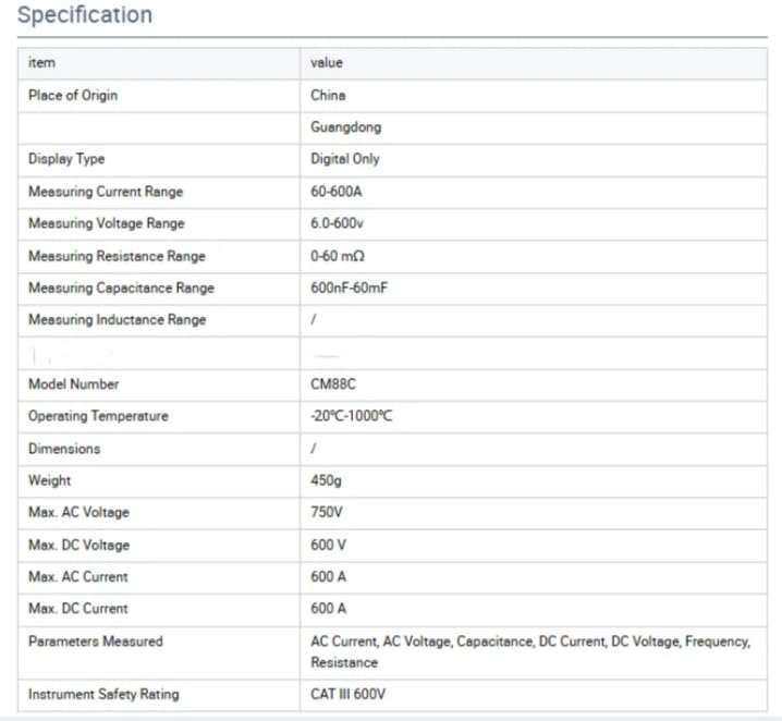
Figure 8.1: Detailed specifications for the CM88C, including measurement ranges and operating conditions.
| Item | Value |
|---|---|
| Place of Origin | China, Guangdong |
| Display Type | Digital Only |
| Measuring Current Range | 60-600A |
| Measuring Voltage Range | 6.0-600V |
| Measuring Resistance Range | 0-60 MΩ |
| Measuring Capacitance Range | 600nF-60mF |
| Model Number | CM88C |
| Operating Temperature | -20°C-1000°C (for thermocouple) |
| Weight | 450g |
| Max. AC Voltage | 750V |
| Max. DC Voltage | 600V |
| Max. AC Current | 600A |
| Max. DC Current | 600A |
| Parameters Measured | AC Current, AC Voltage, Capacitance, DC Current, DC Voltage, Frequency, Resistance, Temperature, Diode, Continuity |
| Instrument Safety Rating | CAT III 600V |
9. Warranty and Support
For warranty information and technical support, please refer to the documentation provided with your purchase or contact your retailer. Keep your purchase receipt as proof of purchase.