
Introduction
This manual provides comprehensive instructions for the installation, operation, and maintenance of the BAOMAIN TBT7-A1 10-Function Time Relay. This versatile device features a high-capacity single-pole double-throw (1-SPDT) contact and supports a wide power supply range of AC/DC 12V-240V. It offers 10 distinct timing functions, allowing it to replace multiple single-function relays in various industrial automation and OEM machinery applications. The relay is designed for DIN rail mounting and provides a flexible time setting range from 0.1 seconds to 10 days.
Safety Information
Please read and understand all safety instructions before installing or operating this device. Failure to follow these instructions may result in electrical shock, fire, or serious injury.
- Electrical Hazard: Installation and maintenance should only be performed by qualified personnel.
- Power Disconnection: Always disconnect power to the circuit before installing, wiring, or servicing the relay.
- Voltage Compatibility: Ensure the supply voltage matches the specifications of the relay (AC/DC 12V-240V).
- Load Capacity: Do not exceed the maximum contact current rating of 16A.
- Proper Wiring: Use appropriate wire gauges and ensure all connections are secure to prevent overheating and short circuits.
- Environmental Conditions: Operate the relay within its specified temperature and humidity ranges.
Product Overview
The BAOMAIN TBT7-A1 is a compact, DIN rail mountable time relay. It features three rotary switches for setting the time range, percentage of the range, and the desired function mode. Dual LED indicators provide visual feedback: a green LED for power (Un) and a red LED for output relay status (R).
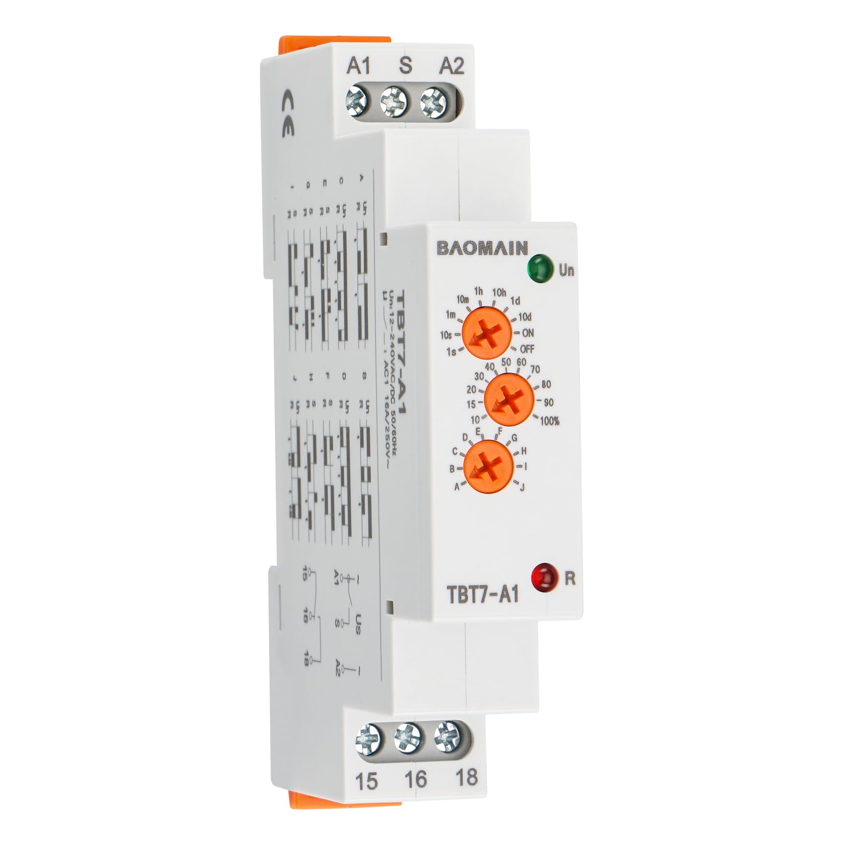
Front view of the BAOMAIN TBT7-A1 10-Function Time Relay, showing the control dials and terminal connections.

Close-up of the BAOMAIN TBT7-A1 time relay's control dials, illustrating the time range and percentage settings. The top dial selects the time unit (seconds, minutes, hours, days), and the middle dial sets the percentage within that range.
Official product video demonstrating the features and functions of the Baomain TBT7-A1 Multi-Function Time Relay, including an overview of its components and operational modes.
Installation and Wiring
Mounting
The TBT7-A1 time relay is designed for standard 35mm DIN rail mounting. Simply clip the relay onto the DIN rail until it securely locks into place. Ensure adequate ventilation around the unit.
Wiring Connections
The relay features screw terminals for secure electrical connections. Refer to the diagram below for proper wiring. The terminals are labeled as follows:
- A1, A2: Power Supply Terminals (Un)
- S: Control Terminal (Trigger Input)
- 15: Common Contact for Output Relay
- 16: Normally Closed (NC) Contact
- 18: Normally Open (NO) Contact
The control terminal 'S' is activated by connecting it to the A1 terminal via an external control contact. The A2 terminal can power a load (e.g., relay, lamp, contactor) which remains powered when 'S' is closed.

Diagram showing the internal relay contact configuration and an example external wiring diagram for the TBT7-A1 time relay.
Operating Instructions
Setting Time and Function
The TBT7-A1 relay features three rotary switches on its front panel for configuration:
- Time Range Selector: The top dial selects the base time unit (e.g., 1s, 1m, 1h, 1d) and the maximum duration (e.g., 10s, 10m, 10h, 10d).
- Percentage Selector: The middle dial adjusts the time duration as a percentage (0-100%) of the selected time range.
- Function Mode Selector: The bottom dial selects one of the 10 available timing functions (A-J).
Function Modes (A-J)
The TBT7-A1 offers 10 distinct timing functions. Refer to the diagram below for a visual representation of each function's behavior. 'Un' represents the supply voltage, 'S' is the trigger terminal, and 'R' is the output contact status.

Detailed diagram illustrating the 10 different timing functions (A-J) of the TBT7-A1 relay, showing input (Un, S) and output (R) states over time.
| Mode | Description |
|---|---|
| A: On Delay (Power on) | Upon input voltage (Un) application, timing delay 't' begins. Relay contacts change state after delay 't' is complete. Contacts return to their shelf state when input voltage Un is removed. Trigger switch 'S' is not used in this function. |
| B: Interval (Power on) | Upon input voltage (Un) application, relay contacts 'R' change state immediately and timing cycle 't' begins. When delay 't' is complete, contacts return to their shelf state. If input voltage Un is removed, contacts will also return to their shelf state. Trigger switch 'S' is not used in this function. |
| C: Repeat Cycle (Starting off) | When input voltage Un is applied, time delay 't' begins. When time delay 't' is complete, relay contacts 'R' change state for time delay 't'. This cycle will repeat until input voltage Un is removed. Trigger switch 'S' is not used in this function. |
| D: Repeat Cycle (Starting on) | When input voltage Un is applied, relay contacts 'R' change state immediately and time delay 't' begins. When time delay 't' is complete, contacts return to their shelf state for time delay 't'. This cycle will repeat until input voltage Un is removed. Trigger switch 'S' is not used in this function. |
| E: Off Delay (S Break) | Input voltage Un must be applied continuously. When trigger switch 'S' is closed, relay contacts 'R' change state. When trigger switch 'S' is opened, delay 't' begins. When delay 't' is complete, contacts 'R' return to their shelf state. If trigger switch 'S' is closed before delay 't' is complete, then timer resets. If trigger switch 'S' is opened, the delay begins again. The relay contacts 'R' remain in their energized state. If input voltage Un is removed, relay contacts 'R' return to their shelf state. |
| F: Single Shot | Upon application of input voltage Un, the relay is ready to accept trigger signal 'S'. Upon application of the trigger signal 'S', the relay contacts 'R' transfer and the preset time 't' begins. During time-out, the trigger signal 'S' is ignored. The relay resets by applying the trigger switch 'S' when the relay is not energized. |
| G: Single Shot Trailing Edge (Non-Retriggerable) | Upon application of input voltage Un, the relay is ready to accept trigger signal 'S'. Upon application of the trigger signal 'S', the relay contacts 'R' transfer and the preset time 't' begins. At the end of the preset time 't', the relay contacts 'R' return to their normal condition unless the trigger switch 'S' is opened and closed prior to time-out. If 'S' is closed before preset time elapses, the continuous cycling of the trigger switch 'S' at a rate faster than the preset time will cause the relay contacts 'R' to remain closed. If input voltage Un is removed, relay contacts 'R' return to their shelf state. |
| H: On/Off Delay | Input voltage Un must be applied continuously. When trigger switch 'S' is closed, time delay 't' begins. When time delay 't' is complete, relay contacts 'R' change state and remain transferred until trigger switch 'S' is opened. If input voltage Un is removed, relay contacts 'R' return to their shelf state. |
| I: Latching relay | Input voltage Un must be applied continuously. Output changes state with every trigger switch 'S' closure. If input voltage Un is removed, relay contacts 'R' return to their shelf state. |
| J: Pulse generator | Upon application of input voltage Un, a single output pulse of 0.5 seconds is delivered to relay 'R' for time delay 't'. Power must be removed and re-applied to repeat pulse. Trigger switch 'S' is not used in this function. |
Maintenance
The BAOMAIN TBT7-A1 time relay is designed for long-term, reliable operation with minimal maintenance. To ensure optimal performance:
- Regular Inspection: Periodically check the relay for any signs of physical damage, loose connections, or discoloration.
- Cleaning: Keep the unit free from dust and debris. Use a soft, dry cloth for cleaning. Do not use abrasive cleaners or solvents.
- Environmental Control: Ensure the operating environment remains within the specified temperature and humidity limits to prevent premature wear.
Troubleshooting
If you encounter issues with your TBT7-A1 time relay, consider the following common troubleshooting steps:
- No Power Indication (Green LED Off): Check the power supply connections (A1, A2) and ensure the voltage is within the 12-240V AC/DC range. Verify the power source is active.
- Output Not Activating (Red LED Off/Incorrect):
- Verify the selected function mode (A-J) is appropriate for your application.
- Check the time range and percentage settings.
- For functions requiring a trigger (S terminal), ensure the trigger signal is correctly applied and functioning.
- Inspect the load wiring (terminals 15, 16, 18) for correct connections and continuity.
- Inaccurate Timing: Ensure the time range and percentage dials are set precisely. The repeat accuracy is specified as <0.2%.
- Intermittent Operation: Check all wiring connections for looseness or corrosion. Ensure the relay is not exposed to excessive vibration or extreme temperatures.
If problems persist after performing these checks, contact customer support for further assistance.
Technical Specifications
| Specification | Value |
|---|---|
| Model | TBT7-A1 |
| Power Supply | AC/DC 12V-240V (50/60Hz) |
| Contact Type | 1-SPDT (1 NO 1 NC) |
| Current Rating | 16 A |
| Maximum Switching Voltage | 240V AC |
| Minimum Switching Voltage | 250V AC (for contact rating) |
| Time Range | 0.1 seconds to 10 days (adjustable) |
| Timing Functions | 10 (A-J) |
| Repeat Accuracy | <0.2% |
| Mounting Type | 35mm DIN Rail |
| Operating Temperature | -20°C to +55°C |
| Wattage | 1.3 watts |
| Connector Type | Screw Terminals |
| Contact Material | Copper |
| Included Components | Timer Relay, Instruction Manual |
| Certification | CE |
Warranty and Support
BAOMAIN products are manufactured to high-quality standards and are warranted against defects in materials and workmanship for a period specified at the time of purchase. Please retain your proof of purchase for warranty claims.
For technical support, troubleshooting assistance, or warranty inquiries, please contact your retailer or the manufacturer directly. Provide your product model number (TBT7-A1) and a detailed description of the issue to facilitate prompt service.