
1. Introduction
The AYWHP ESP32-S3 DevC-1-N16R8-S3 development board is a powerful tool designed for Internet of Things (IoT) applications. It integrates Wi-Fi and Bluetooth connectivity, making it versatile for various projects. Featuring two USB Type-C interfaces, it offers flexible options for power supply and data communication. The board's rich interface design includes multiple GPIO pins, I2C, SPI, and UART interfaces, allowing for easy connection to a wide range of sensors and peripherals. Compatible with various development environments, this board is suitable for both beginners and experienced developers looking to implement diverse projects.
2. Key Features
- Low Power Performance: Utilizes the efficient ESP WROOM module, providing excellent Wi-Fi and Bluetooth connectivity, ideal for Arduino IoT projects.
- Dual Download Mode: Equipped with two USB Type-C interfaces for flexible power and data connections, supporting both direct USB and USB-to-serial downloads.
- Easy Programming and Debugging: The ESP32-S3 module can be programmed and flashed via the two USB Type-C ports, offering options for USB or UART mode.
- Secure and Energy Efficient: Supports low-power applications and incorporates various security features to meet stringent security requirements, ensuring longer battery life.
- Multiple Connection Options: Supports Wi-Fi and Bluetooth 5.0 (LE), and includes a port for an external antenna, making it suitable for a variety of smart devices and IoT applications.
3. Hardware Overview
The ESP32-S3 DevC-1-N16R8-S3 board is designed for ease of use and integration. Below are detailed views of its components and layout.

Figure 3.1: Hardware Introduction. This image provides an annotated overview of the development board, highlighting key components such as the RST (Reset) button, BOOT button, PWR LED, TX/RX LEDs, USB-to-serial port (CH343P), USB-C ports for serial and OTG, the WROOM-1 module, power chip, and integrated RGB-LED module.

Figure 3.2: Development Board Details. A close-up view emphasizing critical components: the WROOM-1 chip, the dedicated power chip, and the dual USB Type-C ports for connectivity.

Figure 3.3: Front and Back Views. This image displays both the front and back sides of the development board, illustrating the component layout on the front and the ESP32-S3 module on the reverse side.
4. Physical Dimensions
Understanding the physical dimensions is crucial for integrating the development board into custom enclosures or projects.
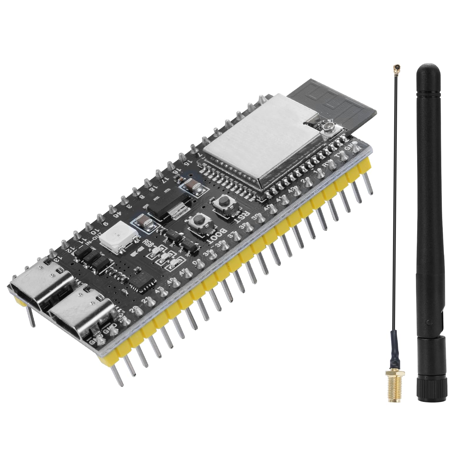
Figure 4.1: Development Board Dimensions. A top-down view of the ESP32-S3 development board with precise measurements in millimeters and inches, indicating its compact form factor.
5. Pinout and System Architecture
The following diagrams illustrate the pin assignments and the internal block structure of the ESP32-S3 DevC-1-N16R8-S3 development board.

Figure 5.1: Development Board Pinout. A detailed image of the development board with color-coded pin labels for 3.3V, RST, GND, TX, RX, and various GPIO pins, indicating their positions on the board headers. Users should refer to this diagram for connecting external components.

Figure 5.2: Development Board Block Diagram. A simplified block diagram illustrating the internal connections and components of the DevKitC-1, including the WROOM-1 module, USB-to-UART bridge, LDO (Low-Dropout Regulator), USB port, RGB LED, and header blocks.
6. Technical Specifications
| Feature | Specification |
|---|---|
| Microcontroller Chip | ESP32-S3-WROOM-1-N16R8 |
| CPU | Dual-Core Xtensa LX7 32-bit |
| Clock Frequency | Up to 240 MHz |
| Flash Memory | 16 MB (built-in) |
| RAM | 512 KB |
| Wireless Connectivity | Wi-Fi 802.11 b/g/n (2.4 GHz), Bluetooth 5.0 (BLE) |
| I/O Pins | 34 GPIO |
| Analog-to-Digital Converter (ADC) | 12-bit resolution, 18 channels |
| Digital-to-Analog Converter (DAC) | 8-bit resolution (Note: See Section 8 for clarification) |
| UART Interfaces | 3 |
| SPI Interfaces | 2 |
| I2C Interfaces | 2 |
| PWM Channels | 16 |
| Operating Voltage | 3.3 V |
| Power Supply | USB-C or external 5 V |
| USB Interface | For programming and debugging (2 ports) |
7. Setup and Initial Programming
This section guides you through the basic steps to set up and program your ESP32-S3 DevC-1-N16R8-S3 development board.
- Connect Power and Data: Use a USB Type-C cable to connect the board to your computer. The board features two USB Type-C ports; one typically functions as a USB-to-serial converter for programming and debugging, while the other can be used for USB OTG or direct USB functionality of the ESP32-S3.
- Driver Installation: Your operating system may require drivers for the USB-to-serial chip (e.g., CH343P). These drivers are usually available from the chip manufacturer's website or can be automatically installed by some development environments.
- Development Environment Setup: The board is compatible with various development environments, including the Arduino IDE, ESP-IDF, and MicroPython. Install the necessary board support packages or toolchains for your chosen environment. For Arduino IDE, add the ESP32 board manager URL and install the ESP32-S3 boards.
- Upload Your Code: Select the correct board model (e.g., ESP32-S3 Dev Module) and the appropriate COM port in your development environment. You can then upload your firmware or sketches to the board. The board supports dual download modes, allowing flexible programming.
- External Antenna: If using the external antenna, ensure it is securely connected to the IPEX connector on the board for optimal wireless performance.
8. Important Notes and Known Discrepancies
Users should be aware of the following points and potential discrepancies in documentation:
- Pinout Documentation: There have been reports of discrepancies between the silkscreen labels on the PCB and some published pinout diagrams. Always cross-reference with official Espressif ESP32-S3 documentation and, if uncertain, verify pin functionality with a multimeter or simple test code before connecting sensitive components.
- Wi-Fi Band: The ESP32-S3 chip supports Wi-Fi 802.11 b/g/n, which operates exclusively in the 2.4 GHz band. Despite some descriptions mentioning "dual-band Wi-Fi," the ESP32-S3 does not support 5 GHz Wi-Fi.
- Digital-to-Analog Converter (DAC): While some specifications might list an 8-bit DAC, the ESP32-S3 typically does not feature an integrated hardware DAC. It has ADC inputs but usually relies on PWM for analog output simulation. Please verify specific chip capabilities if DAC functionality is critical for your application.
- WROOM Module Variant: The product is described as using an ESP32-S3-WROOM-1-N16R8 module with an external antenna connector. Standard WROOM-1 modules usually feature a PCB antenna, while WROOM-1U variants include an external antenna connector. Ensure the module on your board matches the expected functionality for the external antenna.
9. Troubleshooting
If you encounter issues with your ESP32-S3 DevC-1-N16R8-S3 development board, consider the following troubleshooting steps:
- Power Issues: Ensure the board is receiving adequate power. Check the USB Type-C cable and port. Try a different cable or port. The PWR LED should illuminate when power is supplied.
- Connectivity Problems: If your computer doesn't recognize the board, verify that the USB-to-serial drivers are correctly installed. Check your device manager for any unrecognized devices or driver errors.
- Programming Errors: If code upload fails, ensure you have selected the correct board and COM port in your IDE. Try holding the BOOT button while pressing and releasing the RST button, then release BOOT to enter download mode.
- Pinout Discrepancies: As noted in Section 8, verify the actual pin functionality if you suspect a mismatch between documentation and the physical board. Incorrect pin connections can lead to unexpected behavior or damage.
- Wi-Fi/Bluetooth Issues: Ensure your external antenna is properly connected. Check your code for correct initialization of Wi-Fi or Bluetooth modules. Remember that Wi-Fi operates only on 2.4 GHz.
- Component Damage: Visually inspect the board for any signs of physical damage, such as bent pins, burnt components, or solder bridges.
10. Safety Information
Please observe the following safety guidelines when working with the development board:
- Static Electricity: Handle the board with care to prevent damage from electrostatic discharge (ESD). Use an anti-static wrist strap or work on an anti-static mat.
- Power Supply: Only use power supplies that meet the specified voltage (3.3V operating, 5V input via USB-C or external). Exceeding the maximum voltage can damage the board.
- Short Circuits: Avoid short circuits between pins or components. Double-check your wiring before applying power.
- Heat: Some components may generate heat during operation. Ensure adequate ventilation and avoid touching hot components.
- Environment: Do not expose the board to moisture, extreme temperatures, or corrosive environments.
11. Warranty and Support
For warranty information or technical support, please refer to the retailer or manufacturer's official website. Keep your proof of purchase for any warranty claims. For community support, online forums and resources for ESP32 development are widely available.