
1. Introduction
Thank you for choosing the Ortis Above Ground Smart Pool Timer. This device is designed to automate the operation of your pool pump and salt system, enhancing energy efficiency and simplifying your pool maintenance routine. Featuring dual waterproof outlets, a clear LCD display, and flexible timing functions, this timer is built for reliable outdoor performance. Please read this manual thoroughly before installation and operation to ensure proper use and to maximize the lifespan of your product.
2. Safety Information
- Electrical Safety: Always ensure the timer is connected to a properly grounded outlet. Do not immerse the timer in water.
- Maximum Load: The total current for all connected appliances must not exceed 15 Amperes (15A). Overloading can cause damage to the timer and connected devices, and poses a fire hazard.
- Outdoor Use: This timer is designed for outdoor use and features waterproof outlets. However, ensure all connections are secure and protected from direct water spray.
- Disconnection: Disconnect power before performing any maintenance or when the timer is not in use for extended periods.
- Children: Keep out of reach of children. This is not a toy.
- Damage: Do not operate the timer if the cord, plug, or housing is damaged. Contact customer support for assistance.
3. Package Contents
Please check the package for the following items:
- Ortis Above Ground Smart Pool Timer (Model KJ-139)
- Instruction Manual
4. Product Overview
Familiarize yourself with the components of your Ortis Smart Pool Timer.

Figure 4.1: Front view of the Ortis Smart Pool Timer, showing the LCD display, control buttons, and dual outlets (S1 and S2).
4.1. Components
- LCD Display: Shows current time, mode, and operational status.
- (M) Mode Button: Cycles through different operating modes (Countdown, 24H Auto Cycle).
- (T) Time Button: Used to set the current time.
- (^) Up Button: Adjusts values upwards.
- (V) Down Button: Adjusts values downwards.
- Lock Button: Locks/unlocks the display to prevent accidental changes.
- (Manual) Button: Manually turns outlets S1/S2 ON or OFF.
- (Time ON) Button: Used in 24H Auto Cycle mode to set ON times.
- (Power) Button: Turns the timer unit ON/OFF.
- S1 & S2 Outlets: Dual waterproof outlets for connecting appliances.
- Power Cord: Connects the timer to a wall outlet.

Figure 4.2: Detailed view of the LCD screen, showing time, mode, and status indicators.

Figure 4.3: View of the waterproof outlet covers, designed for outdoor protection.
5. Setup
5.1. Mounting the Timer
- Choose a suitable location near your pool or water feature, ensuring it is within reach of a grounded outdoor power outlet and your appliances.
- Mount the timer securely to a wall or sturdy post using appropriate screws (not included). Ensure it is at a height that allows for easy access to the display and buttons, and that the outlets face downwards to prevent water ingress.
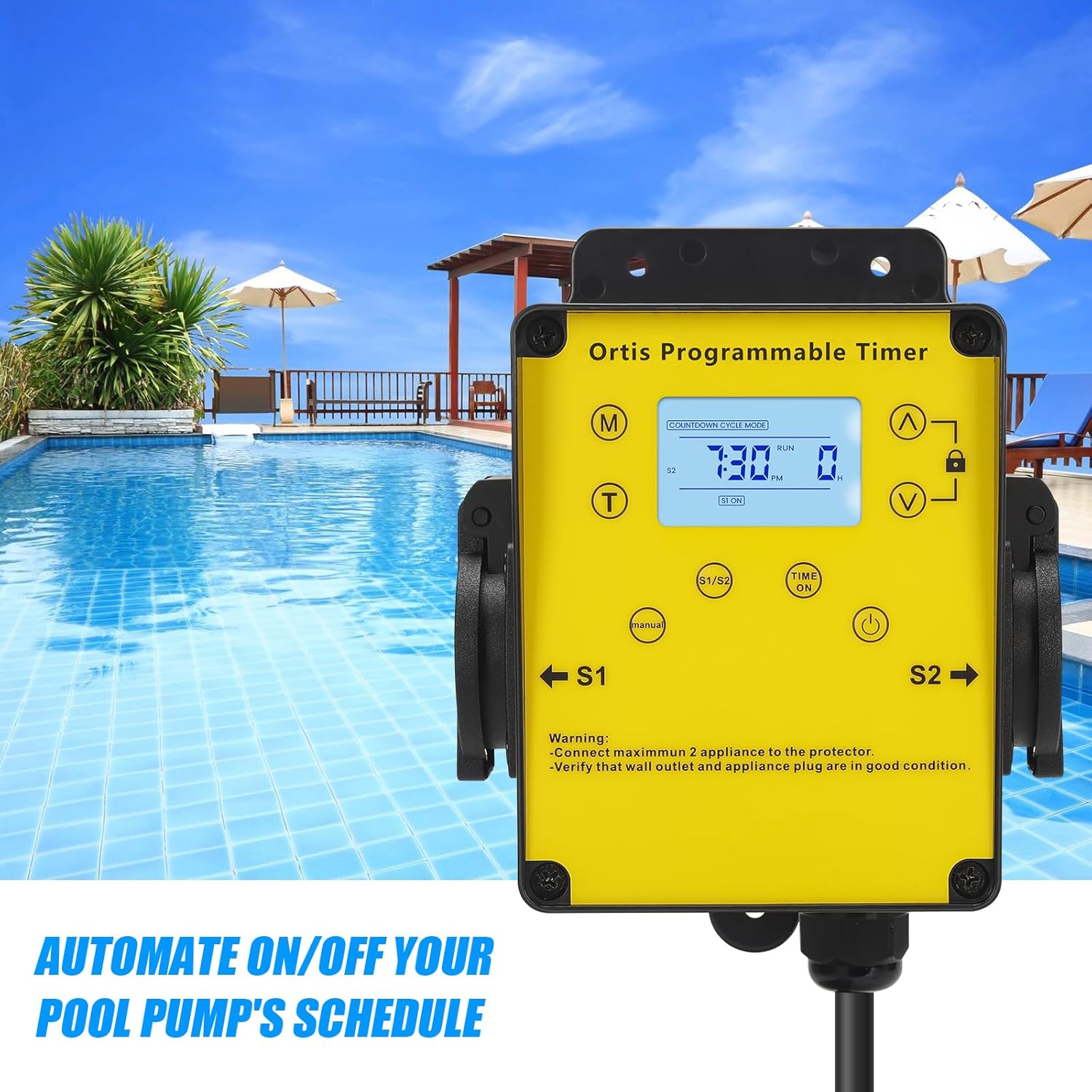
Figure 5.1: The timer mounted on a wall, positioned for convenient access near a pool.
5.2. Connecting to Power
- Plug the timer's power cord into a grounded 120V AC outdoor electrical outlet.
- The LCD display should illuminate. If not, press the Power button.
5.3. Connecting Appliances
- Open the waterproof covers for outlets S1 and S2.
- Plug your pool pump into one outlet (e.g., S1) and your salt system or other appliance into the other outlet (e.g., S2).
- Ensure the total current draw of all connected appliances does not exceed 15A.
- Close the waterproof covers securely around the appliance plugs to maintain weather resistance.

Figure 5.2: The timer with a pool pump and salt chlorinator connected to its dual outlets.
6. Operating Instructions
6.1. Setting Current Time
- Press and hold the (T) Time button until the hour digits flash.
- Use the (^) Up and (V) Down buttons to adjust the hour. Pay attention to AM/PM.
- Press the (T) Time button again to move to minute adjustment. Use (^) Up and (V) Down to set minutes.
- Press the (T) Time button one more time to confirm and exit time setting.
6.2. Countdown Mode
This mode allows you to set a specific duration for the connected appliances to run before automatically turning off.
- Press the (M) Mode button until "COUNTDOWN CYCLE MODE" appears on the display.
- The hour digits for the countdown will flash. Use the (^) Up and (V) Down buttons to set the desired running hours.
- Press the (M) Mode button again to move to minute adjustment. Use (^) Up and (V) Down to set the desired running minutes.
- Press the (M) Mode button once more to confirm the countdown duration.
- The timer will now display the countdown. The connected appliances will turn ON and run for the set duration, then turn OFF automatically.
6.3. 24H Auto Cycle Mode
This mode allows you to program daily ON/OFF schedules for your appliances.
- Press the (M) Mode button until "24H AUTO CYCLE MODE" appears on the display.
- Press the (Time ON) button to enter program setting. The display will show "1 ON".
- Use the (^) Up and (V) Down buttons to set the desired ON time (hour and minute). Press (Time ON) to switch between hour and minute.
- After setting the ON time, press (Time ON) again. The display will show "1 OFF".
- Use the (^) Up and (V) Down buttons to set the desired OFF time (hour and minute). Press (Time ON) to switch between hour and minute.
- You can set multiple ON/OFF programs (e.g., 2 ON, 2 OFF, etc.) by repeating steps 3-5. The timer supports multiple programs.
- Once all programs are set, press the (M) Mode button to exit program setting and activate the 24H Auto Cycle mode. The timer will now follow your programmed schedule daily.
6.4. Manual Override
To manually turn the connected appliances ON or OFF, regardless of the programmed schedule:
- Press the (Manual) button. Each press will cycle through ON, OFF, and AUTO modes for the outlets.
- In AUTO mode, the timer will follow the programmed schedule.
6.5. Lock Function
To prevent accidental changes to settings:
- Press and hold the Lock button for approximately 3 seconds to lock the keypad. A lock icon will appear on the display.
- Repeat the action to unlock the keypad. The lock icon will disappear.
7. Maintenance
- Cleaning: Disconnect the timer from power before cleaning. Wipe the exterior with a soft, damp cloth. Do not use abrasive cleaners or solvents.
- Inspection: Regularly inspect the power cord, plug, and outlets for any signs of damage or wear. Ensure waterproof covers are intact and properly sealed.
- Storage: If storing the timer for an extended period, disconnect it from power, clean it, and store it in a dry, cool place away from direct sunlight.
8. Troubleshooting
| Problem | Possible Cause | Solution |
|---|---|---|
| Timer display is off or not responding. | No power; Timer is off; Internal battery low. | Ensure the timer is plugged into a live outlet. Press the Power button. If the problem persists, contact support. |
| Appliances not turning ON/OFF as programmed. | Incorrect program settings; Timer in Manual mode; Appliances not properly connected. | Verify program settings in 24H Auto Cycle mode. Ensure the timer is in AUTO mode (not Manual). Check appliance plugs are fully inserted into the timer outlets. |
| Appliances not receiving power in any mode. | Overload; Faulty appliance; Timer malfunction. | Check if the total load exceeds 15A. Test appliances directly in a wall outlet. If they work, the timer may be faulty. Contact support. |
| Keypad is unresponsive. | Keypad is locked. | Press and hold the Lock button for 3 seconds to unlock the keypad. |
9. Specifications
- Model: KJ-139
- Input Voltage: 120V AC, 60Hz
- Max Load: 15A / 1800W
- Outlets: 2 Grounded Outlets
- Operating Modes: Countdown, 24H Auto Cycle, Manual
- Display: LCD
- Dimensions (H x W x D): Approximately 4.9" x 3.3" x 3.9"
- Power Cord Length: Approximately 4.7 ft
- Environmental Rating: Outdoor Rated, Waterproof Outlets

Figure 9.1: Product dimensions of the Ortis Smart Pool Timer.
10. Warranty and Support
10.1. Warranty Information
Ortis products are manufactured to high-quality standards. This product is covered by a limited warranty against defects in materials and workmanship from the date of purchase. Please retain your proof of purchase for warranty claims. The warranty does not cover damage caused by misuse, improper installation, unauthorized repairs, or natural disasters.
10.2. Customer Support
If you have any questions, require assistance with setup, or encounter any issues not covered in this manual, please contact Ortis customer support. Refer to the product packaging or the Ortis brand store on Amazon for contact details.