
1. Introduction
This manual provides essential information for the safe and effective use of your RioRand 7-70V PWM DC Motor Speed Controller 30A. This device is designed to provide precise speed control for brushed DC motors, making it suitable for various DIY projects, small electric tools, fans, and mini pumps. It features an optimized circuit design with a high-voltage MOSFET and 3x 100V capacitors to ensure stable performance, low heat generation, and smooth speed adjustments from 1% to 100% duty cycle. An extra fuse is included for your convenience.
2. Safety Instructions
Please read and understand all safety instructions before operating the device to prevent damage or injury.
- This controller is designed exclusively for brushed DC motors. It is not compatible with brushless motors or AC power sources.
- Ensure the input DC power polarity is correct. Reverse connection will cause permanent damage to the controller.
- Do not exceed the maximum input voltage of 70V. It is recommended to reserve a 5-10V voltage margin to prevent overload.
- Match your motor's power requirements to the controller's voltage-specific limits (e.g., 12V≤250W, 24V≤350W) to avoid overloading the device.
- For accurate output voltage measurement, always connect a loaded motor to the output terminals. No-load readings will typically match the input voltage.
- Disconnect power before performing any installation, wiring, or maintenance.
- Keep the device away from moisture, extreme temperatures, and flammable materials.
3. Product Overview
The RioRand 7-70V PWM DC Motor Speed Controller features a robust design for reliable performance.
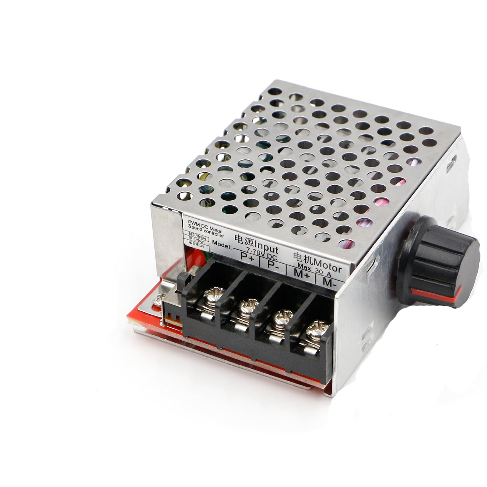
Image: The RioRand 7-70V PWM DC Motor Speed Controller, featuring an aluminum housing, input/output terminals, and a potentiometer for speed adjustment.
Key Features:
- Wide Voltage & High Current: Supports 7-70V DC input and up to 30A current, with a 1%-100% duty cycle (12kHz PWM).
- Low Heat & Durable Design: Equipped with a high-voltage MOSFET, three 100V capacitors, and an aluminum housing for efficient heat dissipation and long-term stability.
- Accurate Voltage Measurement: Output voltage should be measured with a loaded motor for correct readings.
- Easy Wiring & Safe Operation: Features clear input/output terminals, an on-board run/stop/brake switch, and a detachable 15cm potentiometer wire.
- Trusted Performance: Provides smooth speed transitions, overload current protection, and stable operation for various applications.
4. Setup and Wiring
Follow these steps for proper installation and wiring of your motor speed controller.
- Prepare for Installation: Ensure all power sources are disconnected before beginning any wiring.
- Connect Input Power: Connect your DC power supply (7-70V) to the controller's input terminals. Pay close attention to polarity: connect the positive (+) terminal of the power supply to the positive input terminal of the controller, and the negative (-) terminal to the negative input terminal. Incorrect polarity will damage the device.
- Connect Motor: Attach your brushed DC motor to the controller's output terminals. The motor's polarity is not critical for operation; if you need to reverse the motor's direction, simply swap the motor wires connected to the output terminals.
- Connect Potentiometer: The detachable 15cm potentiometer is used for speed adjustment. Connect its cable to the designated port on the controller.
- Secure Connections: Double-check all wiring connections to ensure they are secure and properly insulated.
- Apply Power: Once all connections are verified, you may safely apply power to the controller.
5. Operating Instructions
Once the controller is properly wired and powered, you can begin operation.
- Speed Adjustment: Rotate the knob on the potentiometer to adjust the motor's speed. Turning the knob clockwise will increase the speed, while turning it counter-clockwise will decrease it. The speed can be adjusted from 1% to 100% of the motor's maximum speed.
- Run/Stop/Brake Switch: Use the on-board switch to control the motor's state. Refer to the markings on the controller for specific functions (e.g., Run, Stop, Brake).
- Direction Reversal: To change the direction of the motor's rotation, power off the controller, then swap the two wires connecting the motor to the controller's output terminals. Reapply power to resume operation in the new direction.
6. Maintenance
Regular maintenance helps ensure the longevity and optimal performance of your speed controller.
- Fuse Replacement: An extra fuse is included with your controller. If the device stops functioning, check the fuse. If it is blown, replace it with a fuse of the same type and rating. Always disconnect power before replacing the fuse.
- Cleaning: Keep the controller's housing and ventilation openings free from dust and debris. Use a soft, dry cloth for cleaning. Do not use liquid cleaners or solvents.
- Storage: When not in use, store the controller in a dry, cool, and well-ventilated area, away from direct sunlight and corrosive substances.
- Connection Check: Periodically inspect all wiring connections to ensure they remain tight and free from corrosion.
7. Troubleshooting
If you encounter issues with your RioRand DC Motor Speed Controller, refer to the table below for common problems and solutions.
| Problem | Possible Cause | Solution |
|---|---|---|
| Controller not powering on | Incorrect input polarity Blown fuse No power supply | Verify input wiring polarity Check and replace fuse Ensure power supply is connected and active |
| Motor not spinning or weak performance | No load connected (for testing) Incorrect motor wiring Motor fault Overload | Connect a motor to the output Verify motor connections Test motor separately Reduce load or check power limits |
| Output voltage matches input when unloaded | Normal operation for PWM controllers | This is expected. Connect a motor to the output for accurate measurement of effective voltage. |
| Motor speed unstable or noisy | Overload Incompatible motor type Poor connections | Reduce load or check power limits Ensure a brushed DC motor is used Check all wiring connections for tightness |
8. Specifications
Technical specifications for the RioRand 7-70V PWM DC Motor Speed Controller 30A.
| Feature | Detail |
|---|---|
| Input Voltage Range | 7-70V DC |
| Maximum Current | 30A |
| PWM Frequency | 12kHz |
| Duty Cycle Adjustable Range | 1% - 100% |
| Maximum Output Power | 500W |
| Voltage-Specific Power Limits | 12V≤250W, 24V≤350W, 48V≤450W, 60V≤400W |
| Compatible Motor Type | Brushed DC Motors Only |
| Housing Material | Aluminum |
| Model Number | 7-70V PWM DC |
| UPC | 774300117910 |
| Item Weight | 0.15 Kilograms |
9. Warranty and Support
Warranty and specific support information for this product were not available in the provided data. Please refer to the retailer or manufacturer's website for the most current warranty terms and customer support contact details.