
1. Introduction
This manual provides essential information for the safe and efficient operation of your QNK 5.5KW (7.5HP) 380V Variable Frequency Drive (VFD). The VFD is designed for precise speed control of various equipment, including spindle motors, CNC routers, milling machines, pumps, compressors, and grinders. It incorporates advanced PMW control technology for low-noise operation and reduced electromagnetic interference.
The VFD features robust safety mechanisms including overload, fuse, over-voltage, under-voltage, restart, stall, short circuit, and overheat protection. Its construction includes copper coil internals and a non-flammable exterior, along with a multi-grid design for efficient heat dissipation and protection against dust and water mist.

Image: QNK VFD highlighting its multiple protection features including overload, overheat, over-voltage, low-voltage, fuse, stall, and short circuit protection.
2. Safety Guidelines
- Risk of Electric Shock: Always ensure the power supply is disconnected before installation or maintenance. Wait at least 5 minutes for capacitor discharge after disconnecting power.
- Read Manual: Thoroughly read this manual before installing or operating the VFD.
- Personal Protective Equipment (PPE): Always wear appropriate PPE before powering up or working with the VFD.
- Motor Compatibility: Ensure the rated frequency of your motor is consistent with that of the VFD. Adjust VFD parameters (F005, F004, F003) if necessary to match your motor's specifications (e.g., 400Hz for spindle motors).
- Heavy Loads: For heavy-load applications, select a VFD with a higher power rating than your motor.
- Power Source: The VFD cannot be used as a power source for other equipment. Do not drive motors with a supply voltage lower than 90V.
- Capacitive Loads: Do not connect the VFD's output terminals to capacitive loads.
- Generator Power: If using a generator, ensure its output voltage is within +/-15% of the VFD's input voltage.
3. Setup and Installation
3.1 Physical Dimensions

Image: Technical drawing showing the external and installation dimensions of the QNK VFD. Dimensions are 220mm (8.7") height, 118mm (4.6") width, and 148mm (5.8") depth.
3.2 Wiring Connections
Refer to the VFD Connection Diagram for detailed wiring instructions. Ensure all connections are firm and correct before powering on the device.

Image: Detailed VFD Connection Diagram illustrating terminals for power input (L1, L2, L3), brake resistor (DC+, DB), and motor output (U, V, W), along with multi-function digital input, analog output, and RS485 communication interface.
- Power Input: For a 380V single-phase power supply, connect the power wires to terminals L1 and L3. For three-phase, connect to L1, L2, L3.
- Motor Output: Connect the three motor wires to the U, V, and W terminals.
- Braking Resistor (Optional): This VFD supports an external braking resistor (not included). Connect the resistor to the DC+ and DB terminals. A braking resistor helps dissipate energy generated by the motor during deceleration, enabling faster braking for equipment like lifting machinery or engraving machine spindles (e.g., 24,000 RPM stop within 0.5-2 seconds).
- Remote Control Panel: The VFD features a separate control panel for convenient remote operation.

Image: The QNK VFD unit with its detachable control panel, showing how it can be separated for remote control applications.
3.3 Initial Parameter Settings
The VFD's default rated frequency is 50 Hz. For motors with different rated frequencies (e.g., 400 Hz for many spindle motors), you must adjust the following parameters:
- Set F005: Adjust the F005 parameter to match your motor's rated frequency (e.g., 400.0 for 400 Hz).
- Set F004: Adjust the F004 parameter to match your motor's rated frequency (e.g., 400.0 for 400 Hz).
- Set F003: Adjust the F003 parameter to match your motor's rated frequency (e.g., 400.0 for 400 Hz).
- Set F144: Adjust the F144 parameter to match your motor's maximum RPM (e.g., 24000 for 24000 RPM).
If your motor drives high torque equipment, consider increasing the acceleration and deceleration times to prevent motor stress.
Video: QNK VFD Introduction and Setup Process. This video demonstrates the wiring and initial parameter settings for the VFD, including adjusting frequency and RPM settings for a spindle motor.
4. Operating Instructions
4.1 Control Panel Functions

Image: Diagram of the QNK VFD control panel, detailing the function of each button: SET (menu/parameter confirmation), ESC (return), UP/DOWN (modify/select parameters), SHIFT (monitor status/switch digit), F/R (change motor direction), RUN (start command), STOP (stop/reset command).
4.2 Frequency Setting Modes
The VFD supports multiple frequency setting modes:
- Digital Setting: Adjust frequency directly via the control panel buttons.
- Analog Setting: Use an external analog signal for frequency control.
- Serial Communication Setting: Utilize the RS485 communication port with standard international MODBUS main circuit control.
- PID Setting: Advanced calculus PID closed-loop arithmetic for quick response and high suitability in specific applications.
5. Maintenance
Regular maintenance ensures the longevity and optimal performance of your VFD.
- Cooling System: The VFD features an independent air duct design with a powerful cooling fan for strong cooling effect. Ensure the cooling vents are clear of obstructions to allow for fast heat dissipation.
- Environmental Protection: The multi-grid design helps prevent dust and water mist from entering the circuit board section. Periodically inspect and clean the exterior to maintain this protection.
- Internal Components: The VFD is built with copper coil internals and high-capacity capacitors for durability and temperature/pressure resistance. Avoid exposing the unit to extreme conditions.
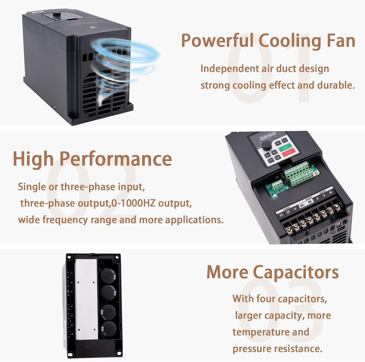
Image: Internal view of the QNK VFD highlighting its powerful cooling fan, high-performance single or three-phase input/output, and multiple capacitors for enhanced capacity and resistance.
6. Troubleshooting
This section provides solutions for common issues. For complex problems, contact QNK customer support.
- Motor Not Running: Check power connections (L1, L3 for single-phase, L1, L2, L3 for three-phase) and motor connections (U, V, W). Verify parameter settings (F005, F004, F003, F144) match motor specifications.
- Overload/Overheat: Ensure the VFD's power rating is sufficient for the motor and application. Check for proper ventilation and clear any obstructions from cooling vents.
- Abnormal Noise: Verify all wiring is secure and correctly terminated. Check for proper grounding.
- Incorrect Speed: Recheck frequency parameter settings (F005, F004, F003) and RPM setting (F144). Ensure the control mode (digital, analog, serial) is correctly configured.
- VFD Error Codes: Consult the full product manual for a comprehensive list of error codes and their corresponding troubleshooting steps.
7. Specifications
| Feature | Specification |
|---|---|
| Brand | QNK |
| Model | 5.5KW (7.5HP) 380V VFD |
| Input Voltage | 1-phase/3-phase 380 VAC (+/- 15%) |
| Input Current | 0-12.5 A |
| Input Frequency | 50/60 Hz |
| Output Voltage | 3-phase 380 VAC |
| Output Current | 0-12.5 A |
| Output Frequency | 0-2,000 Hz |
| Power (Wattage) | 5.5 KW (7.5 HP) |
| Peak Output Power | 5500 Watts |
| Dimensions (L x W x H) | 8.6 x 4.6 x 5.8 inches (220mm x 118mm x 148mm) |
| Control Technology | PMW Control, V/F Control, Vector Control, PID Control |
| Communication | RS485 (MODBUS) |
| Protection Features | Overload, Fuse, Over-voltage, Under-voltage, Restart, Stall, Short Circuit, Overheat |
| Recommended Uses | CNC Routers, Compressors, Grinders, Milling Machines, Pumps, Spindle Motors |
8. Warranty and Support
Information regarding product warranty and customer support details is not provided in the available product data. Please refer to the product packaging or contact the manufacturer directly for warranty claims and technical assistance.
