
1. Product Overview
The BSIDE UX1 is a compact, intelligent TRMS clamp meter designed for precise current measurement, smart multimeter functions, and voltage detection. It is ideal for troubleshooting low-current circuits, diagnosing automotive battery discharge, and testing parasitic draw in HVAC systems. This device allows for AC and DC current measurement without breaking the circuit.
Key Features:
- High Precision: Measures AC/DC current from 0 to 100A with 1mA resolution.
- Zero Function: For accurate low current measurements and detecting hidden battery leaks.
- Smart Multimeter: Automatic and manual measurement of AC/DC voltage, resistance, continuity, capacitance, diodes, duty cycle, frequency, and temperature.
- Non-Contact Voltage (NCV) Detection: With audible and visual alerts.
- Live Wire Identification: For enhanced safety during electrical inspections.
- Large Color LCD Display: Bright, easy-to-read display with TRMS value indication.
- Rechargeable Battery: Integrated 3.7V 400mA rechargeable battery for extended use.
- Automatic Range Selection: With overload protection.
- Compact Design: Mini size (192 × 45.8 × 30 mm) and lightweight (122g) for portability.

Image 1.1: The BSIDE UX1 Clamp Meter in use, showing a current measurement on its clear display.
2. Package Contents
Upon opening the package, please ensure all the following items are present:
- BSIDE UX1 Clamp Meter
- Test Leads (Red and Black)
- Charging Cable
- K-Type Thermocouple
- EVA Carrying Case
- English User Manual (PDF in French available via email)

Image 2.1: All items included in the BSIDE UX1 Clamp Meter package, including the meter, test leads, charging cable, thermocouple, and case.
3. Setup
3.1 Charging the Device
The BSIDE UX1 Clamp Meter is equipped with an internal rechargeable battery. Before first use, or when the low battery indicator appears, connect the device to a USB power source using the provided charging cable.
- Locate the charging port on the side of the clamp meter.
- Insert the small end of the charging cable into the meter's port.
- Connect the other end of the charging cable to a standard USB power adapter (not included) or a computer USB port.
- The battery indicator on the display will show charging status.

Image 3.1: The BSIDE UX1 Clamp Meter being charged via its USB port.
3.2 Power On/Off
Press and hold the power button (usually marked with a ⑂ symbol) to turn the device on or off.
4. Operating Instructions
4.1 Automatic Mode Selection
The BSIDE UX1 features an intelligent automatic mode that simplifies measurements for beginners. In this mode, the meter automatically detects and measures AC/DC voltage, resistance, and continuity.
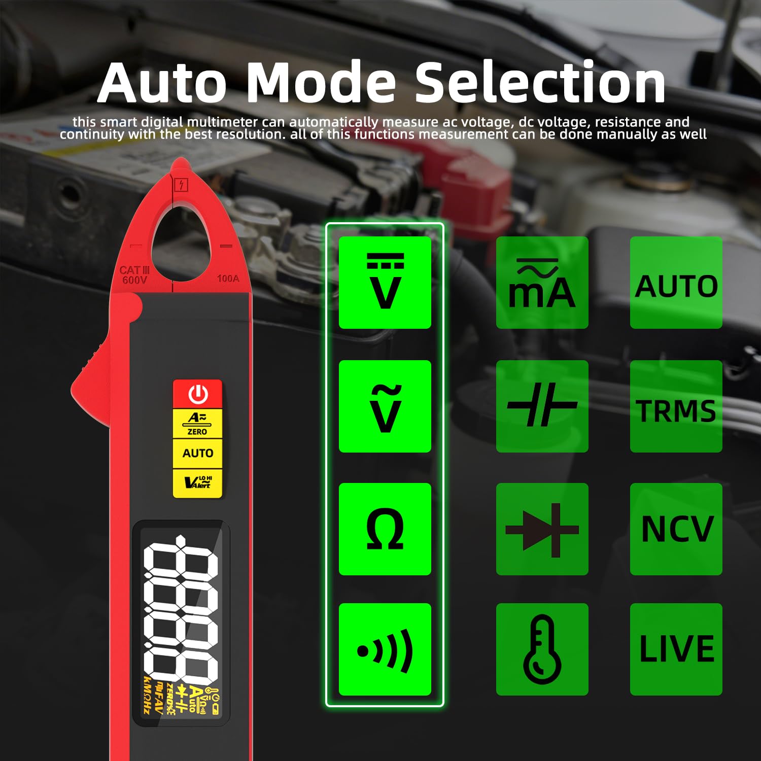
Image 4.1: The display indicating automatic mode selection and available measurement functions.
4.2 Manual Measurement Functions
For specific measurements, you can manually select functions such as capacitance, diodes, frequency, temperature, and duty cycle. Refer to the on-screen indicators and buttons for mode selection.
4.3 Current Measurement (AC/DC)
To measure AC or DC current, open the clamp jaws and enclose a single conductor. Ensure the conductor is centered within the jaws for accurate readings. The device will display the current value with 1mA resolution.
Important Note on Hall Effect and Zeroing:
The clamp meter operates on the Hall Effect principle. For precise measurements, especially of low currents, follow these steps:
- Before testing, press the 'ZERO' button to reset the display to zero. This compensates for signals from the Earth's electromagnetic field. If zeroing is unsuccessful, repeat the process several times.
- After zeroing, do not rotate the clamp meter; maintain the same orientation.
- Perform the test within 5 seconds of zeroing. Beyond this time, the clamp meter may detect new electromagnetic field signals, affecting accuracy.
4.4 Voltage Detection (NCV)
The Non-Contact Voltage (NCV) function allows for safe detection of AC voltage without direct contact. Bring the NCV sensor (located at the top of the clamp) close to the conductor. The device will emit audible and visual alerts if voltage is detected.

Image 4.2: The clamp meter detecting voltage using its NCV function, indicated by visual alerts.
4.5 Live Wire Check
To identify live wires, use the provided test leads. Insert the red test lead into the 'INPUT' jack and the black test lead into the 'COM' jack. Touch the red probe to the conductor. The display will indicate if the wire is live.

Image 4.3: The clamp meter performing a live wire check with test leads.
4.6 Temperature Measurement
Connect the K-type thermocouple to the meter's input jacks to measure temperature. The device supports a wide range from -50 ℃ to 1000 ℃.

Image 4.4: The clamp meter measuring temperature using the K-type thermocouple.
5. Maintenance
5.1 Cleaning
Wipe the device with a dry, soft cloth. Do not use abrasive cleaners or solvents. Ensure the device is powered off before cleaning.
5.2 Battery Care
To prolong battery life, charge the device regularly, especially if it will be stored for an extended period. Avoid fully discharging the battery frequently.
5.3 Storage
Store the clamp meter in its provided EVA carrying case in a cool, dry place, away from direct sunlight and extreme temperatures. Keep it out of reach of children.
6. Troubleshooting
6.1 Inaccurate Current Readings
- Zeroing: Ensure you perform the zeroing procedure (Section 4.3) before each current measurement, especially for low currents. Repeat if necessary.
- Orientation: Do not rotate the clamp meter after zeroing; maintain a consistent orientation during measurement.
- Time Limit: Complete the measurement within 5 seconds after zeroing to avoid interference from external electromagnetic fields.
- Single Conductor: Ensure only one conductor is enclosed within the clamp jaws. Measuring multiple conductors will result in incorrect readings.
6.2 Device Not Powering On
- Battery Charge: Check if the battery is sufficiently charged. Connect the device to a charger and allow it to charge for at least 30 minutes before attempting to power on again.
- Power Button: Ensure the power button is pressed and held for a few seconds.
6.3 Display Issues
- Low Battery: If the display is dim or flickering, the battery may be low. Recharge the device.
- Overload Indication: If 'OL' is displayed, the measured value exceeds the meter's range. Disconnect immediately to prevent damage.
7. Specifications
| Parameter | Specification |
|---|---|
| Display | 6000 Counts |
| DC Current Range | 0.001-5.999 A / 59.99 A / 100 A |
| DC Current Resolution | 0.001 A / 0.01 A / 0.1 A |
| AC Current Range | 0.001-5.999 A / 59.99 A / 100 A |
| AC Current Resolution | 0.001 A / 0.01 A / 0.1 A |
| DC Voltage Range | 0.001-5.999 V / 59.99 V / 599.9 V / 610 V |
| AC Voltage Range | 0.050-5.999 V / 59.99 V / 599.9 V / 610 V |
| Resistance Range | 0.1-599.9 Ω / 5.999 kΩ / 59.99 kΩ / 599.9 kΩ / 5.999 MΩ / 60 MΩ |
| Capacitance Range | 0.010-5.999 µF / 59.99 µF / 599.9 µF / 5.999 mF / 60 mF |
| Frequency Range | 1.000-9.999 Hz / 99.99 Hz / 999.9 Hz / 999.9 kHz / 9.999 MHz |
| Temperature Range | -50 ℃ to 1000 ℃ |
| Diode Test | Less than 3V |
| Duty Cycle | 10% - 95% |
| NCV | Audible signal |
| Continuity | Buzzer sounds if resistance is less than 50 Ω |
| Power Supply | Rechargeable 3.7V 400mA Battery |
| Dimensions | 192 × 45.8 × 30 mm |
| Weight | 122 g |
| Safety Compliance | UL 61010-1, IEC 61010-2-030, CE marking |
8. Warranty and Support
For warranty information, please refer to the documentation provided at the time of purchase or contact your retailer. For technical support or further inquiries, please refer to the contact information provided with your product or on the manufacturer's official website. A detailed PDF manual in French is available via email upon request.


