
Introduction
This manual provides comprehensive instructions for the Generic PWM150 Programmable Dual-Channel Signal Generator. This device is designed for precise control of frequency, duty cycle, and phase, making it suitable for a wide range of applications including electronics laboratories, industrial automation, educational training, and DIY projects.
The PWM150 features independent dual-channel control with phase linkage, a clear dual-screen display, and multiple LED indicators for intuitive operation. Its compact and portable design ensures ease of use in various environments.
Safety Information
Please read and understand all safety instructions before operating the device. Failure to follow these instructions may result in electric shock, fire, or damage to the product.
- Ensure the power supply voltage is within the specified range (5-24 VDC).
- Do not expose the device to moisture or extreme temperatures.
- Avoid short-circuiting the output terminals.
- Do not attempt to disassemble or modify the device. Refer all servicing to qualified personnel.
- Keep the device away from flammable materials.
Product Overview
The Generic PWM150 is a compact and versatile signal generator. Below is an illustration of its main components and controls.

Figure 1: Front view of the PWM150 Signal Generator with labeled controls and indicators. Key components include the rotary encoder, MOD, SYNC, SET, and OUT buttons, dual digital displays for frequency and duty cycle/phase, and LED indicators for channels (CH1, CH2) and output (OUT).
- Rotary Encoder: Used to adjust parameters. Press briefly to switch between digit positions (with flashing indication). Rotate to adjust the selected parameter value.
- MOD Key: Switches between channels (CH1/CH2) or changes the duty cycle/phase display in synchronous mode.
- SYNC Button: Enables dual-channel parameter synchronization and supports frequency, duty cycle, and phase linkage adjustment.
- SET Key: Accesses system settings (Power-on Output, Parameter Saving/Retrieval, Frequency/Duty Cycle Upper/Lower Limit Settings).
- OUT Key: One-click start/stop PWM signal output. A green LED indicates the output status.
- CH1/CH2 LEDs: Indicate the currently selected channel.
- OUT LED: Indicates if the output signal is active.
- Digital Displays: Show frequency (in kHz) and duty cycle (in %) or phase (in °).
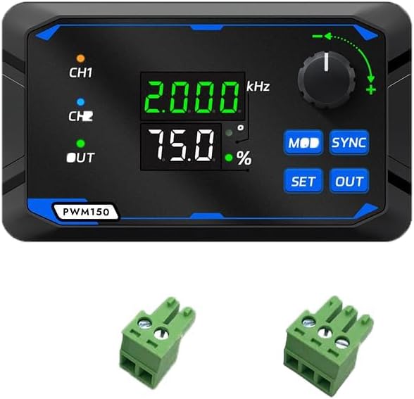
Figure 2: Top-down view of the PWM150 Signal Generator, showing the two green screw terminal connectors for output signals.
Specifications
| Feature | Specification |
|---|---|
| Product Name | Programmable PWM Signal Generator |
| Brand | Generic |
| Model Number | 0E2ATSVAM2UK42AN3FJ8 |
| Dimensions | 120 mm x 80 mm x 25 mm (approx. 12 x 8 x 2.5 cm) |
| Weight | 94 g |
| Duty Cycle Accuracy | 0% - 100%, 0.1% step adjustment |
| Rise Time | 20 ns |
| Phase Adjustment | 0° - 360° (1° step, synchronous mode available) |
| Output Voltage | 5-24 VDC |
| Maximum Output Current | 0.2 A |
Setup
- Unpacking: Carefully remove the signal generator and any accessories from its packaging. Inspect for any signs of damage.
- Power Connection: Connect a 5-24 VDC power supply to the designated power input terminals. Ensure correct polarity.
- Output Connection: Connect your load or circuit to the CH1 and/or CH2 output terminals using appropriate wiring. The device comes with screw terminal connectors for easy wiring.
- Initial Power-On: Once power is connected, the device display should illuminate, showing default frequency and duty cycle values.

Figure 3: The PWM150 Signal Generator shown with its two green screw terminal connectors, which are used for connecting power and output signals.
Operating Instructions
This section details how to operate the PWM150 signal generator to achieve desired output signals.
1. Basic Parameter Adjustment (Frequency, Duty Cycle)
- Select Channel: Press the MOD key to switch between CH1 and CH2. The corresponding LED (CH1 or CH2) will illuminate.
- Adjust Frequency: The upper display shows the frequency. Press the Rotary Encoder briefly. The digit position for frequency adjustment will flash. Rotate the encoder clockwise to increase frequency, counter-clockwise to decrease. Press again to move to the next digit or to confirm.
- Adjust Duty Cycle: The lower display shows the duty cycle (%). Press the MOD key again (if in frequency adjustment mode) or press the Rotary Encoder until the duty cycle digits flash. Rotate the encoder to adjust the duty cycle from 0% to 100%.
- Start/Stop Output: Press the OUT key to start or stop the PWM signal output for the selected channel. The green OUT LED will indicate the output status.
2. Synchronous Mode and Phase Adjustment
The PWM150 supports synchronous operation of both channels with phase adjustment.
- Enable Sync Mode: Press the SYNC button. The device will enter synchronous mode, linking parameters between CH1 and CH2.
- Adjust Phase: In synchronous mode, the lower display can show phase (in °). Use the MOD key to cycle through duty cycle and phase display. Once phase is displayed, press the Rotary Encoder to select the digit and rotate to adjust the phase from 0° to 360° in 1° steps.
- Linked Parameters: When in synchronous mode, adjustments to frequency or duty cycle on one channel may affect the other, depending on the specific synchronization settings.
3. System Settings (SET Key)
Press the SET key to access advanced settings. These typically include:
- Power-on Output State: Configure whether the output is active or inactive upon power-up.
- Parameter Saving/Retrieval: Save custom settings for quick recall.
- Frequency/Duty Cycle Limits: Set upper and lower limits for parameter adjustments.
Navigate through the settings using the MOD key and adjust values with the Rotary Encoder. Press SET again to exit the settings menu.
Maintenance
- Cleaning: Use a soft, dry cloth to clean the device. Do not use abrasive cleaners or solvents.
- Storage: Store the device in a cool, dry place away from direct sunlight and extreme temperatures when not in use.
- Inspection: Periodically check the wiring and connections for any signs of wear or damage.
Troubleshooting
| Problem | Possible Cause | Solution |
|---|---|---|
| Device does not power on. | No power supply, incorrect voltage, or reversed polarity. | Check power supply connection, ensure voltage is 5-24 VDC, and verify polarity. |
| No output signal. | Output is disabled, incorrect settings, or faulty connection. | Press the OUT key to enable output. Check frequency/duty cycle settings. Verify output wiring. |
| Parameters cannot be adjusted. | Encoder not pressed, or in a locked mode. | Press the Rotary Encoder to select a digit for adjustment. Ensure not in a menu that prevents adjustment. |
| Inaccurate output. | Incorrect calibration (unlikely for new device) or external interference. | Ensure proper grounding. If issues persist, contact support. |
Warranty and Support
For warranty information, please refer to the terms and conditions provided by your retailer or contact the manufacturer directly.
For technical support or inquiries, please contact the seller through the platform where the product was purchased.