
1. Introduction
This manual provides comprehensive instructions for the installation, operation, and maintenance of the Generic M8400T IS7XM V1.0 LGA 1155 DDR3 Desktop Motherboard. Designed for optimal performance and reliability, this motherboard is compatible with a wide range of processors and components, making it suitable for various computing needs. Please read this manual thoroughly before proceeding with installation or operation to ensure proper setup and to prevent damage to the components.
2. Safety Information
Always observe the following safety precautions when handling computer components:
- Electrostatic Discharge (ESD) Prevention: Always wear an anti-static wrist strap or frequently touch a grounded metal object (like the computer case) before handling the motherboard or other components. ESD can severely damage electronic parts.
- Power Disconnection: Ensure the power supply is unplugged from the wall outlet before installing or removing any components.
- Proper Ventilation: Ensure your computer case has adequate airflow to prevent overheating.
- Handle with Care: Hold the motherboard by its edges to avoid touching sensitive components or circuits.
- Professional Assistance: If you are unsure about any installation steps, consult a qualified technician.
3. Product Overview
The Generic M8400T IS7XM V1.0 motherboard is designed for desktop computing, offering a stable and efficient platform. Key features include:
- High-performance design for optimal and efficient computing.
- Durable and reliable construction using high-quality materials.
- Easy installation and broad compatibility with various processors and components.
- LGA 1155 CPU socket support.
- DDR3 RAM technology support.
3.1 Motherboard Layout
Below is an image illustrating the main components and layout of the motherboard.
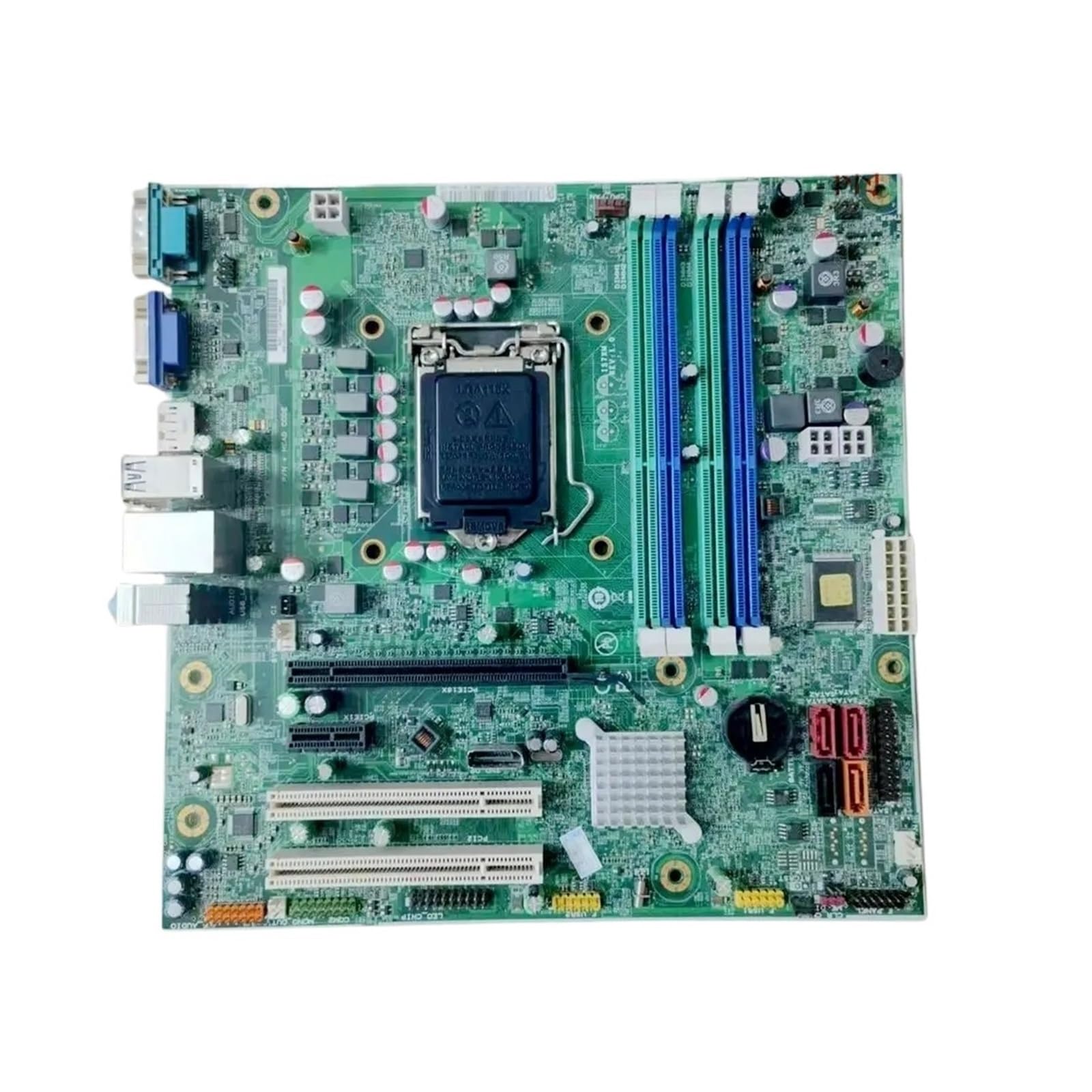
Figure 1: Overview of the Generic M8400T IS7XM V1.0 Motherboard. This image displays the full motherboard, highlighting the central LGA 1155 CPU socket, two blue and green DDR3 RAM slots, various expansion slots (PCIe x16, PCIe x1), SATA ports, and I/O connectors such as USB, Ethernet, and audio ports on the left edge.
Key components include:
- CPU Socket (LGA 1155): Located centrally, this is where the processor is installed.
- DDR3 DIMM Slots: Two slots (blue and green) for installing DDR3 memory modules.
- PCIe Expansion Slots: Includes a PCIe x16 slot for graphics cards and PCIe x1 slots for other expansion cards.
- SATA Ports: Connectors for storage devices like hard drives and SSDs.
- I/O Panel: Rear connectors for peripherals such as USB devices, display outputs (VGA), Ethernet, and audio.
- Power Connectors: Main ATX power connector and CPU power connector.
4. Setup and Installation
Follow these steps carefully to install your motherboard and components.
4.1 Pre-Installation Checklist
- Ensure you have all necessary components: CPU, RAM, CPU cooler, power supply, storage devices, and a compatible computer case.
- Prepare your workspace: a clean, well-lit, and static-free environment.
- Gather tools: Phillips head screwdriver, anti-static wrist strap.
4.2 Motherboard Installation
- Install the I/O shield into the rear opening of your computer case.
- Carefully align the motherboard with the standoffs inside the case.
- Secure the motherboard with screws, ensuring it is firmly seated and not touching any metal parts of the case directly.
4.3 CPU Installation (LGA 1155)
- Open the CPU socket lever and lift the metal load plate.
- Carefully place the CPU into the socket, aligning the golden triangle on the CPU with the triangle on the socket. Do not force it.
- Lower the load plate and secure it by pushing the lever back into place.
- Apply thermal paste to the CPU (if not pre-applied on the cooler) and install the CPU cooler according to its manufacturer's instructions.
4.4 RAM Installation (DDR3)
- Open the clips on both ends of the DDR3 DIMM slots.
- Align the notch on the RAM module with the notch in the DIMM slot.
- Press down firmly on both ends of the RAM module until the clips snap into place.
4.5 Connecting Peripherals and Power
- Connect the 24-pin ATX power connector and the 4-pin or 8-pin CPU power connector from your power supply to the motherboard.
- Connect SATA data cables from your storage devices to the SATA ports on the motherboard.
- Install your graphics card into the PCIe x16 slot and secure it. Connect any necessary PCIe power cables from the power supply to the graphics card.
- Connect front panel headers (power button, reset button, USB ports, audio jacks) to their respective pins on the motherboard. Refer to your case manual for specific pin assignments.
5. Operating Instructions
5.1 First Boot
- After connecting all components and power, plug in your monitor, keyboard, and mouse.
- Turn on the power supply and then press the power button on your computer case.
- The system should power on and display the BIOS/UEFI splash screen.
5.2 BIOS/UEFI Access
To enter the BIOS/UEFI setup utility, press the designated key (commonly Del, F2, or F10) repeatedly during the initial boot sequence. The exact key may vary; check the on-screen prompts during startup.
5.3 Driver Installation
After installing your operating system, install the necessary drivers for the motherboard's chipset, audio, network, and any other integrated components. These drivers are typically provided on a support CD/DVD or can be downloaded from the manufacturer's website.
6. Maintenance
- Dust Cleaning: Regularly clean dust from inside your computer case, especially from fans and heatsinks, using compressed air. Ensure the system is powered off and unplugged before cleaning.
- BIOS/UEFI Updates: Periodically check the manufacturer's website for BIOS/UEFI updates. Updates can improve stability, compatibility, and performance. Follow the update instructions carefully to avoid damaging the motherboard.
- Cable Management: Ensure internal cables are neatly routed to improve airflow and prevent interference.
7. Troubleshooting
If you encounter issues, refer to the following common troubleshooting steps:
- No Power:
- Check if the power supply is properly connected to the wall outlet and the motherboard (24-pin ATX and CPU power).
- Ensure the power supply switch is in the "ON" position.
- Verify front panel power button connection to the motherboard.
- No Display:
- Ensure the monitor is connected to the correct display output (either integrated graphics or dedicated graphics card).
- Reseat the graphics card and RAM modules.
- Try booting with only one RAM stick.
- System Instability/Crashes:
- Check CPU and GPU temperatures.
- Verify RAM is properly seated and functioning.
- Ensure all drivers are up to date.
- Run memory diagnostic tools.
- Component Not Detected:
- Check power and data cable connections for the component.
- Ensure the component is properly seated in its slot.
- Update BIOS/UEFI to the latest version.
8. Specifications
The following table lists the technical specifications for the Generic M8400T IS7XM V1.0 Motherboard:
| Feature | Specification |
|---|---|
| Brand | Generic |
| Model Name | QLAEWRHEE |
| CPU Socket | BGA 1023 (Note: Product description mentions LGA 1155, please verify compatibility with your CPU) |
| RAM Technology | DDR3 |
| Memory Clock Speed | 1 GHz |
| Max RAM Size | 1 GB (Note: This value seems unusually low for a DDR3 motherboard, please verify with seller or manufacturer) |
| Available Memory Slots | 1 (Note: Image shows 2 slots, please verify with seller or manufacturer) |
| CPU Model | Alpha |
| Platform | 3DO |
| Manufacturer Part Number | QLAEWRHEE |
| Country of Origin | China |
Note on Specifications: Some specifications provided (e.g., CPU Socket, Max RAM Size, Available Memory Slots, Platform) appear inconsistent with typical LGA 1155 DDR3 motherboards or the product image. Users are advised to verify these details with the seller or manufacturer before purchase or installation to ensure compatibility with their intended components. The product description mentions LGA 1155 and DDR3, which is generally associated with higher RAM capacities and multiple slots. The "BGA 1023" socket and "1 GB" max RAM are typically for embedded or older systems.
9. Warranty and Support
For warranty information and technical support, please refer to the documentation provided with your purchase or contact the seller directly. Keep your proof of purchase for any warranty claims.