
1. Introduction
The eletechsup ES32G15 is a multi-function expansion board specifically designed for use with the ESP32-DevKitC. This board integrates a variety of analog and digital input/output circuits, including NTC temperature acquisition and RS485 communication capabilities. It is intended to facilitate development and expansion of projects requiring robust I/O and communication features with an ESP32 microcontroller.
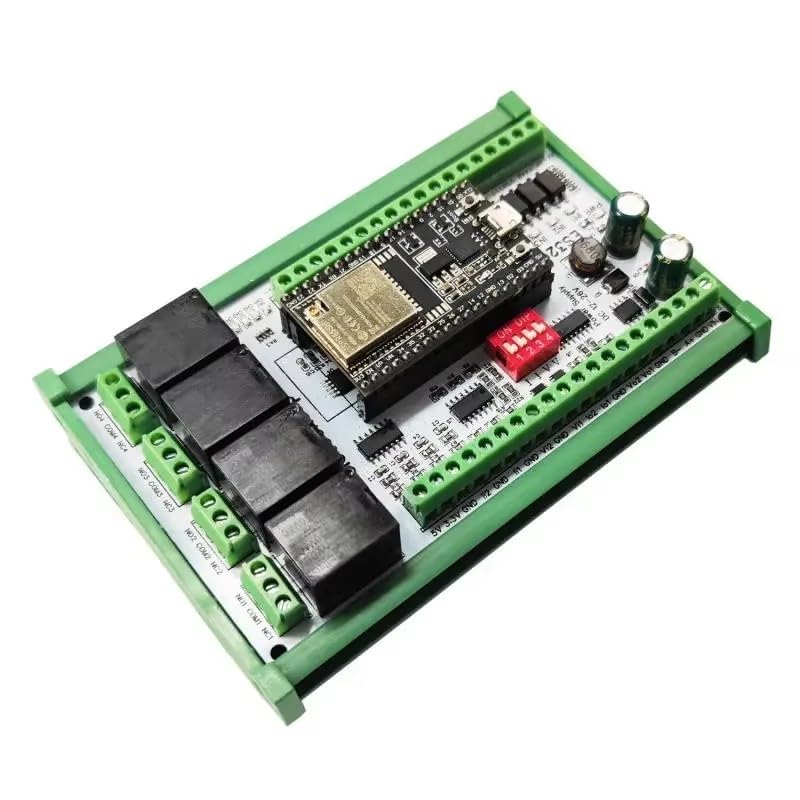
Figure 1: eletechsup ES32G15 Expansion Board (Only Board version)
2. Product Overview and Features
The ES32G15 expansion board offers a comprehensive set of resources to enhance the functionality of your ESP32-DevKitC. Key features include:
- Multi-Function ESP32 Expansion: Designed for ESP32-DevKitC, providing extensive analog and digital I/O, NTC temperature acquisition, and RS485 communication.
- Wide Voltage & Low Power: Operates with a DC 12-28V wide voltage input. Standby current is 15mA, with current consumption increasing based on relay activation (e.g., 4 relays open at 155mA).
- Rich Onboard Resources: Includes 2 channels of 0/4-20mA current output, 2 channels of 0-5V/10V voltage output, 2 channels of 0/4-20mA current input, 2 channels of 0-5V/10V voltage input, 4 channels of 10K NTC input (supports any B value), 4 channels of NPN digital input, 4 channels of 10A relay output, 5 free ports, and 1 RS485 port.
- Easy Development: Pin mapping is conveniently printed on the back of the PCB board. Basic Arduino test codes are provided for hardware verification.
- Compact & Durable: The board measures 121x72x19mm (board only) and weighs 95g (board only). A version with a DIN rail shell is also available, weighing 186g.

Figure 2: Diagram highlighting the rich onboard resources of the ES32G15.
3. Specifications
| Parameter | Value |
|---|---|
| Working Voltage | DC 12-28V (Wide Voltage) |
| Standby Current | 15mA |
| Current (1 Relay Open) | 50mA |
| Current (2 Relays Open) | 85mA |
| Current (3 Relays Open) | 120mA |
| Current (4 Relays Open) | 155mA |
| Dimensions (Board Only) | 121 x 72 x 19mm |
| Weight (Board Only) | 95g |
| Weight (With Shell) | 186g |
| Analog Current Output | 2-channel 0/4-20mA |
| Analog Voltage Output | 2-channel 0-5V/10V |
| Analog Current Input | 2-channel 0/4-20mA |
| Analog Voltage Input | 2-channel 0-5V/10V |
| NTC Input | 4-channel 10K NTC (Any B value) |
| Digital Input | 4-channel NPN Digital Input |
| Relay Output | 4-channel 10A Relay Output |
| Free Ports | 5 channels |
| Communication Port | 1-channel RS485 Port |
4. Setup
The ES32G15 expansion board requires a 38-pin ESP32-DevKitC board to function. It cannot operate independently. Ensure you have a compatible 38-pin ESP32 board before proceeding with the setup. If you do not have one, it must be purchased separately.
4.1 ESP32 Board Compatibility
The ES32G15 supports 38-pin ESP32 boards with two common widths: 22.5mm and 25.4mm. Carefully align the ESP32 board with the header pins on the ES32G15.
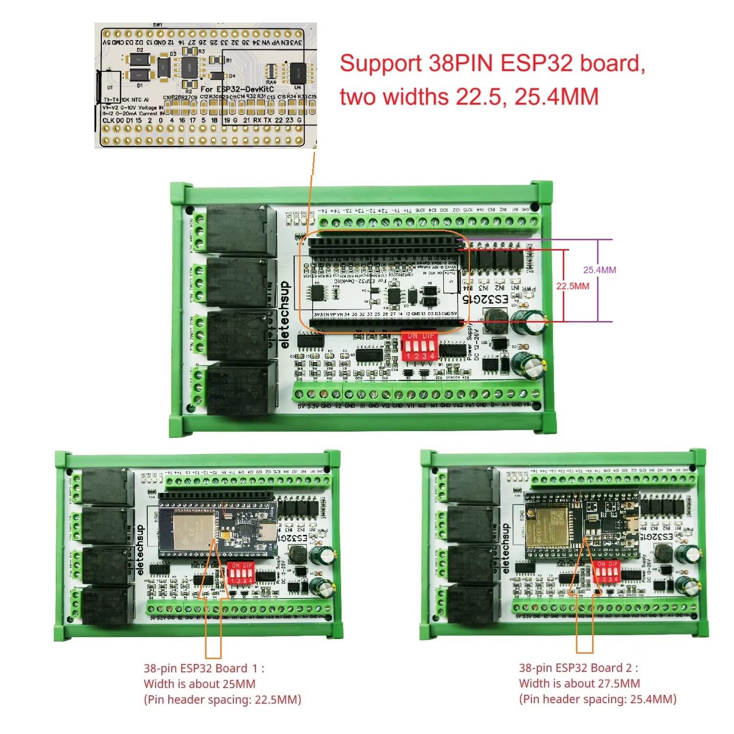
Figure 3: ES32G15 supporting 38-pin ESP32 boards of different widths.
4.2 Pin Mapping
The pin mapping between the ES32G15 expansion board ports and the 38-pin ESP32 pins is crucial for proper programming and operation. Refer to the table below and the diagram for detailed connections.
| ES32G15 Expansion Board Ports | 38PIN ESP32 Pin |
|---|---|
| Vo1-Vo2 (0-10V AO) | IO25/IO26 |
| Io1-Io2 (0-20mA AO) | IO25/IO26 |
| Vi1-Vi2 (0-10V AI) | IO36/IO39 |
| Ii1-Ii2 (0-20mA AI) | IO34/IO35 |
| T1-T4 (10K NTC AI) | IO14/IO27/IO33/IO32 |
| IN1-IN4 (NPN DI) | IO19/IO18/IO5/IO17 |
| CH1-CH4 (Relay DO) | IO12/IO13/IO21/IO23 |
| Free Port | IO15/IO2/IO0/IO4/IO16 |
| RS485 Port | IO1/IO3/IO22 |

Figure 4: Pin mapping and onboard resources diagram.

Figure 5: Back of the ES32G15 board showing printed pin mapping.
4.3 Power Connection
Connect a DC power supply within the 12-28V range to the designated power input terminals on the board. Ensure correct polarity.
4.4 Optional DIN Rail Shell Installation
If using the version with a DIN rail shell, install the board into the shell and mount it onto a compatible DIN rail. This provides protection and simplifies integration into industrial control panels.

Figure 6: ES32G15 board with and without DIN box, and an ESP32 board inserted.
5. Operating Instructions
The ES32G15 board functions as an expansion module for the ESP32-DevKitC. Its operation is entirely dependent on the code uploaded to the connected ESP32 board. eletechsup provides basic Arduino codes for testing the hardware functionalities. For specific applications and advanced features, users are required to develop their own custom code.
5.1 Input/Output Configuration
The board features multiplexed output ports for voltage (Vo1/Vo2) and current (Io1/Io2). Only one of these output types can be enabled at a time for each channel. This selection is made via the SW1 DIP switch on the board. Refer to the detailed diagram for the location and settings of SW1.

Figure 7: Detailed diagram of the ES32G15, showing power interface, RS485, analog I/O, digital I/O, NTC, relay outputs, and the SW1 dip switch for multiplexed output selection.
The 3.3V power output from the board is dependent on the connected ESP32 board and will only be active when the ESP32 board is properly inserted and powered.
5.2 Programming
Utilize the Arduino IDE or other compatible development environments to program your ESP32-DevKitC. Refer to the provided pin mapping to correctly address the various inputs and outputs of the ES32G15 board in your code.
6. Maintenance
To ensure the longevity and reliable operation of your ES32G15 expansion board, follow these general maintenance guidelines:
- Keep Clean: Regularly clean the board to prevent dust and debris accumulation, which can affect performance. Use a soft, dry brush or compressed air.
- Keep Dry: Avoid exposure to moisture or high humidity environments. Water can cause short circuits and damage components.
- Proper Storage: When not in use, store the board in an anti-static bag in a cool, dry place.
- Inspect Connections: Periodically check all wiring and connections for looseness or corrosion.
7. Troubleshooting
If you encounter issues with your ES32G15 expansion board, consider the following troubleshooting steps:
- No Power: Verify that the DC 12-28V power supply is correctly connected and providing the specified voltage. Check for proper polarity.
- ESP32 Not Functioning: Ensure the 38-pin ESP32-DevKitC board is correctly seated on the ES32G15. Confirm that the ESP32 itself is powered and programmed.
- Incorrect I/O Readings/Outputs: Double-check your code for correct pin assignments according to the pin mapping table. Verify the SW1 DIP switch settings for multiplexed outputs (Vo/Io).
- Communication Issues (RS485): Confirm RS485 wiring and termination. Check the ESP32 code for correct RS485 initialization and communication protocols.
- Relay Malfunction: Ensure the relay control pins are correctly configured in your ESP32 code. Check the power supply for sufficient current to activate all relays.
8. Support
eletechsup provides basic Arduino codes for testing the hardware functionalities of the ES32G15. Please note that eletechsup does not provide additional code development or technical support beyond the initial hardware testing examples. Users are responsible for developing their own application-specific code and functionalities.


