
1. Introduction
This manual provides detailed instructions for the BANRIA ZK-DMC02 PWM DC Motor Speed Controller. This device is designed for precise control of DC brushed motors, offering variable speed regulation, forward/reverse capabilities, and multiple operational modes. Please read this manual thoroughly before installation and operation to ensure safe and efficient use.
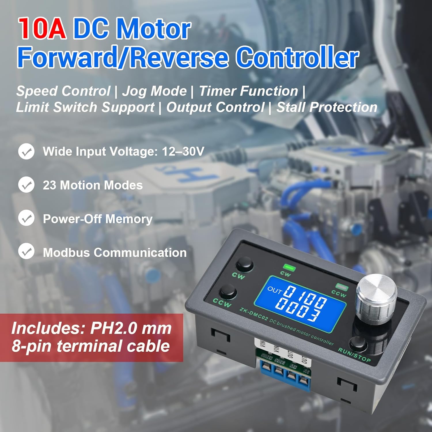
Image 1.1: The BANRIA ZK-DMC02 PWM DC Motor Speed Controller, showcasing its compact design and key features such as wide input voltage (12-30V), 23 motion modes, power-off memory, and Modbus communication.
Key Features:
- Dedicated DC Motor Forward & Reverse Control: Specifically designed for DC motors, supporting a wide DC 12–30V input range. Utilizes an H-bridge drive design with a maximum effective current of up to 10A for stable operation.
- 23 Built-in Motion Modes: Features 23 preset motion modes, including speed control, jog operation, delay, cycle, forward/reverse rotation, and output control.
- Power-Off Memory: Retains settings such as speed, run time, delay time, and cycle count after power loss. Cycle count is adjustable from 1 to 9999.
- Modbus Communication & Multiple Control Methods: Supports Modbus communication and TTL serial control. Can operate standalone or integrate into automation systems with automatic, manual, parameter setting, and serial control modes.
- Multiple Protections & Expansion Interfaces: Includes stall protection, adjustable overcurrent protection, and reverse polarity input protection. Provides interfaces for power supply, buttons, limit switches, and outputs.
2. Safety Information
Please observe the following safety precautions to prevent injury or damage to the device:
- Ensure the input voltage is within the specified range of DC 12V-30V.
- Do not exceed the maximum effective current of 10A.
- Verify all wiring connections are correct and secure before applying power. Incorrect wiring can damage the controller or motor.
- This product is suitable for general industrial control applications. It is not intended for medical, fire protection, or life-critical uses.
- Avoid operating the device in environments with excessive moisture, dust, or extreme temperatures outside the specified operating range (-10°C to 60°C).
- Disconnect power before performing any maintenance or wiring changes.
3. Product Overview
3.1 Component Identification

Image 3.1: Front panel of the ZK-DMC02 controller. It features a CW button for forward rotation, a CCW button for reverse rotation, corresponding indicator lights, a digital display, an encoder setting knob, and a RUN/STOP button.
- CW Button: Initiates forward rotation.
- CCW Button: Initiates reverse rotation.
- CW Indicator: Lights up when the motor is rotating forward.
- CCW Indicator: Lights up when the motor is rotating in reverse.
- Digital Display: Shows speed, time, mode, and other parameters.
- Encoder Setting Knob: Used to adjust parameters and navigate menus. Press to confirm, rotate to change values.
- RUN/STOP Button: Starts or stops motor operation.
3.2 Internal Components and Connections

Image 3.2: Internal layout and connection points of the ZK-DMC02 controller. Key terminals include VIN+/VIN- for power supply, OUT+/OUT- for motor connection, and an 8-pin expansion interface for external controls.
- VIN+/VIN-: Power supply input terminals (DC 12V-30V).
- OUT+/OUT-: Motor output terminals.
- Expand 8P Interface: Multi-functional expansion port.
- 12V+/12V-: 12V power output from the expansion interface.
- Start/Stop: External trigger input for start/stop functionality.
- Switch direction/emergency stop: External trigger input for changing direction or emergency stop.
- Limit1/Limit2: Inputs for limit switches.
- Output1/Output2: 2-channel output signals (0V, requires common anode connection 12V).
3.3 Serial Port Output

Image 3.3: Serial port output pins for TTL serial communication, including 5V, TXD, RXD, and GND.
4. Specifications
| Parameter | Value | Parameter | Value |
|---|---|---|---|
| Product Model | ZK-DMC02 | Load Capacity | 0-10A DC brushed motor |
| Operating Voltage | DC 12-30V | Drive Method | H-Bridge |
| Control Modes | 23 motion modes | Communication Protocol | MODBUS |
| Protection Features | Adjustable over-current protection, Stall protection, Reverse polarity input protection | Expansion Interface | Power supply, Buttons, Limit switches, Output port |
| Product Dimensions | 79 × 43 × 30 mm (3.11 x 1.69 x 1.18 inches) | Operating Temperature | -10°C to 60°C (non-condensing) |
| Product Weight | Net weight 70g, with packaging 90g | Main Functions of the System | Automatic, manual, setting, serial port control |
| Cycle Work Times | 1-9999 times | Remote Communication Control | TTL serial port |
5. Setup and Wiring
5.1 Basic Wiring Diagram
Connect the power supply and motor according to the diagram below. Ensure correct polarity for both input power and motor connections.

Image 5.1: Basic wiring diagram showing connections for the power supply (VIN+/VIN-) and the DC motor (OUT+/OUT-).
- Connect your DC 12V-30V power supply to the VIN+ (positive) and VIN- (negative) terminals.
- Connect your DC motor to the OUT+ and OUT- terminals. The motor direction can be controlled via the CW/CCW buttons or programmed modes.
5.2 Signal, Limit, and Output Connections
The expansion interface allows for integration with external control signals, limit switches, and output devices.

Image 5.2: Detailed wiring for external controls, including start/stop buttons, direction change buttons, limit switches (Limit1, Limit2), and output signals (Y1, Y2).
- Start/Stop Button: Connect a normally open button between the 'Start/Stop' pin and GND on the expansion interface.
- Change Direction Button: Connect a normally open button between the 'Switch direction/emergency stop' pin and GND on the expansion interface.
- Limit Switches: Connect NPN normally open proximity switches to 'Limit1' and 'Limit2' pins. The brown wire connects to 12V, blue to GND, and black to the limit interface.
- Output Signals (Y1, Y2): These are 0V output signals. For external devices, a common anode connection to 12V is required.
Video 5.1: Demonstration of the ZK-DMC02 controller's expand button control function, showing how external buttons can be used for start/stop and direction switching, along with limit switch functionality.
6. Operating Instructions
6.1 Basic Operation
- Start/Stop: Press the RUN/STOP button to start or stop the motor.
- Forward Rotation: Press the CW button to initiate clockwise rotation.
- Reverse Rotation: Press the CCW button to initiate counter-clockwise rotation.
- Speed Adjustment: Rotate the encoder setting knob to change the motor speed while running.
6.2 Parameter Setting Methods
The ZK-DMC02 offers 23 motion modes and various adjustable parameters. Follow these steps to access and modify settings:

Image 6.1: Visual guide for entering parameter setting mode and modifying parameters using the encoder knob and RUN/STOP button.
- Entering Parameter Set Mode: At the running interface, press and hold the encoder setting knob for more than 3 seconds. The display will change to show parameter F-01.
- Selecting Parameters: In Parameter Set Mode, rotate the encoder knob to cycle through parameters F-01 to F-14.
- Modifying Parameter Values:
- Method 1 (Direct Rotation): Press the encoder knob to select a parameter value. Directly rotate the knob to change the value.
- Method 2 (Bit-by-bit Adjustment): Press the encoder knob again, and the selected bit will blink. Rotate the knob to change the value for the blinking bit (0-9). Modify other bits in the same manner. This method improves setup efficiency.
- Saving and Exiting: After adjusting parameters, press and hold the encoder knob for more than 3 seconds to save the settings and exit Parameter Set Mode.
- Return to Running Interface: Press the RUN/STOP button to return to the running interface without saving changes if you are in Parameter Set Mode.
Note: The parameter and parameter value are not the same. Ensure you are modifying the correct value for the selected parameter.
7. Maintenance
To ensure the longevity and optimal performance of your ZK-DMC02 controller, follow these maintenance guidelines:
- Cleaning: Keep the controller clean and free from dust and debris. Use a soft, dry cloth for cleaning. Do not use liquid cleaners or solvents.
- Environment: Operate and store the device in a dry, well-ventilated area within the specified temperature range. Avoid direct sunlight and high humidity.
- Connections: Periodically check all wiring connections to ensure they are secure and free from corrosion. Loose connections can lead to intermittent operation or damage.
- Inspection: Visually inspect the controller for any signs of physical damage, such as cracked casing or burnt components. If damage is found, discontinue use and contact support.
8. Troubleshooting
If you encounter issues with your ZK-DMC02 controller, refer to the following common problems and solutions:
| Problem | Possible Cause | Solution |
|---|---|---|
| Motor does not start | No power supply; Incorrect wiring; Motor fault; Controller in STOP mode. | Check power connections and voltage; Verify motor wiring; Test motor independently; Press RUN/STOP button. |
| Motor runs in wrong direction | Incorrect motor polarity; Incorrect mode setting. | Reverse motor OUT+ and OUT- connections; Check and adjust mode settings (CW/CCW). |
| Inconsistent speed or no speed control | Encoder knob issue; Incorrect parameter setting; Motor overload. | Check encoder knob functionality; Review speed parameters; Reduce motor load. |
| Display not working | No power; Damaged display. | Check power supply; Contact support if display is damaged. |
| Overcurrent protection triggers | Motor stall; Excessive load; Short circuit. | Check for motor obstruction; Reduce load; Inspect wiring for shorts; Adjust overcurrent protection threshold if necessary (refer to parameter settings). |
If the problem persists after attempting these solutions, please contact BANRIA customer support for further assistance.
9. Warranty and Support
BANRIA products are designed for reliability and performance. For warranty information, technical support, or service inquiries, please refer to the product packaging or contact your retailer. Keep your purchase receipt as proof of purchase.
For additional resources and product information, visit the official BANRIA store on Amazon: BANRIA Store