
1. Introduction
This manual provides detailed instructions for the assembly, setup, operation, and maintenance of your MUXWELL HU-052A DIY Music Spectrum LED Light Kit. This kit is designed to offer hands-on experience in electronics and soldering, resulting in a functional audio level indicator with a vibrant LED display. Please read all instructions carefully before beginning assembly.
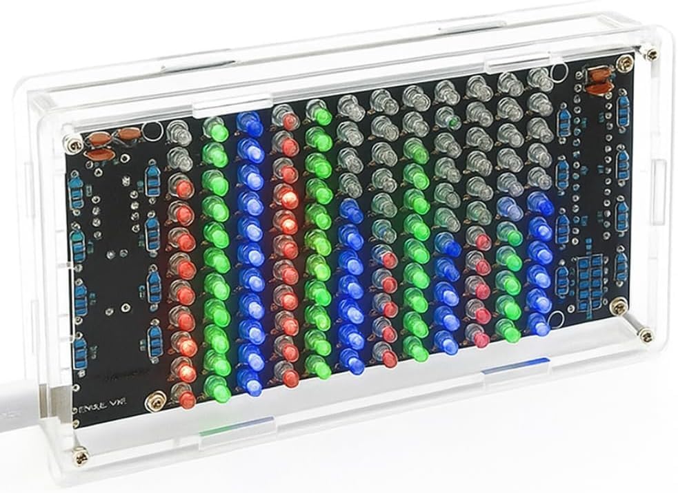
Image: Assembled MUXWELL Music Spectrum LED Light Kit displaying sound levels, with red, green, and blue LEDs illuminating in response to audio input.
2. Safety Information
Working with electronic components and soldering irons requires caution. Please observe the following safety guidelines:
- Always use a soldering iron in a well-ventilated area to avoid inhaling fumes.
- Wear appropriate eye protection to shield against solder splashes or flying component leads.
- Ensure the soldering iron is placed in a stable holder when not in use to prevent accidental burns or damage.
- Allow components and solder joints to cool completely before handling.
- Keep all tools and components out of reach of children and pets.
- Verify correct component polarity and placement before soldering to prevent damage to the circuit.
- Disconnect power before making any adjustments or repairs to the assembled kit.
3. Package Contents
Before starting assembly, verify that all components listed below are present in your kit. If any parts are missing or damaged, please contact customer support.
- Printed Circuit Board (PCB)
- Electronic Components (Resistors, Capacitors, Diodes, Integrated Circuits, Transistors, Microphone, LEDs)
- Acrylic Enclosure Parts
- Fasteners (Screws, Nuts)
- USB Power Cable
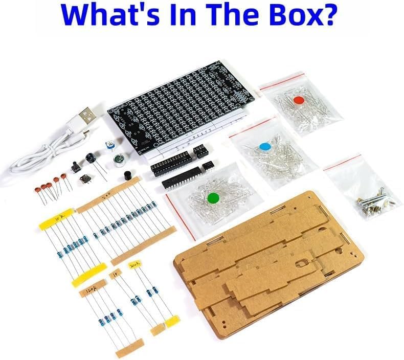
Image: All components of the MUXWELL DIY Music Spectrum LED Light Kit laid out, including the PCB, bags of LEDs, resistors, capacitors, ICs, microphone, acrylic panels, and a USB cable.
4. Assembly Instructions
Follow these steps carefully to assemble your Music Spectrum LED Light Kit. It is recommended to organize all components before you begin soldering.
4.1 Component Identification
Familiarize yourself with the different electronic components. Resistors are identified by color bands, capacitors by their values, and LEDs by their longer positive (+) lead and shorter negative (-) lead, or a flat edge on the body indicating the negative side.
4.2 Soldering Components to PCB
- Resistors: Solder all resistors onto the PCB according to their marked values and positions. Resistors are not polarized, so orientation does not matter.
- Capacitors: Solder the non-polarized capacitors. For polarized electrolytic capacitors, ensure the longer lead (+) matches the '+' marking on the PCB, and the shorter lead (-) matches the '-' or shaded area.
- Diodes: Solder diodes, ensuring the band on the diode matches the band marking on the PCB for correct polarity.
- Integrated Circuits (ICs) Sockets: Solder the IC sockets first. Ensure the notch on the socket aligns with the notch marking on the PCB. This allows for easier replacement of ICs if needed.
- LEDs: This kit contains 120 LEDs. Carefully solder each LED, ensuring the longer lead (anode) goes into the square pad on the PCB and the shorter lead (cathode) goes into the round pad. Incorrect polarity will prevent the LED from lighting up.
- Microphone: Solder the microphone in its designated spot.
- Potentiometer (Sensitivity Adjustment): Solder the potentiometer.
- Buttons and Connectors: Solder any push buttons and the Micro USB power input socket.

Image: Top and bottom views of the MUXWELL Music Spectrum LED Light Kit Printed Circuit Board (PCB), showing component placement on the top side and solder points on the bottom side.
4.3 Assembling the Enclosure
Once all components are soldered to the PCB, assemble the acrylic enclosure:
- Remove protective film from all acrylic panels.
- Carefully align the PCB with the bottom acrylic panel, ensuring the USB port and buttons align with the cutouts.
- Secure the PCB to the bottom panel using the provided screws and nuts.
- Attach the side panels, then the top panel, securing them with the remaining fasteners. Ensure all panels fit snugly to protect the internal components.
Video: Official video demonstrating the assembled MUXWELL DIY Music Spectrum LED Light Kit in operation, showcasing its sound-reactive LED display.
5. Setup
After successful assembly, follow these steps to set up your Music Spectrum LED Light Kit:
- Power Connection: Connect the provided USB power cable to the Micro USB port on the kit. Plug the other end into a 5V DC USB power source (e.g., a phone charger, computer USB port, or power bank).
- Initial Power On: The LEDs should illuminate, indicating the device is powered on. The display will react to ambient sounds picked up by the built-in microphone.

Image: Rear view of the MUXWELL Music Spectrum LED Light Kit PCB, showing the location of the sensitivity adjustment potentiometer, built-in microphone, setting button, and Micro USB power input socket.
6. Operating Instructions
The MUXWELL HU-052A kit is designed for simple operation:
- Automatic Sound Detection: The built-in microphone automatically detects ambient sound and displays a spectrum visualization on the LED grid.
- Sensitivity Adjustment: Use the small potentiometer (usually a blue square component with a screw slot) located on the PCB to adjust the microphone's sensitivity. Turning it clockwise typically increases sensitivity, making the display more reactive to quieter sounds. Turning it counter-clockwise decreases sensitivity.
- Mode Selection (if applicable): If your kit includes a 'Setting Button' (SW1), short presses may cycle through different display modes or patterns. Refer to the circuit diagram for specific button functionality.
7. Maintenance
The MUXWELL HU-052A kit requires minimal maintenance:
- Cleaning: Use a soft, dry cloth to gently wipe the acrylic enclosure. Avoid abrasive cleaners or solvents that could scratch or damage the acrylic.
- Storage: Store the kit in a dry, dust-free environment when not in use.
- Component Check: Periodically inspect solder joints for any signs of cracking or corrosion. Re-solder if necessary.
8. Troubleshooting
If you encounter issues with your kit, refer to the following troubleshooting guide:
| Problem | Possible Cause | Solution |
|---|---|---|
| No LEDs light up | No power, faulty USB cable, incorrect power source, short circuit, or incorrectly soldered main IC. | Check USB connection and power source (must be 5V). Inspect PCB for solder bridges or cold joints. Verify IC orientation and soldering. |
| Some LEDs do not light up | Incorrect LED polarity, faulty LED, or cold solder joint. | Check the polarity of the unlit LEDs. Re-solder the connections. If still unlit, replace the LED. |
| LEDs are always on or unresponsive | Microphone sensitivity too high/low, faulty microphone, or issue with control circuit. | Adjust the sensitivity potentiometer. Ensure the microphone is correctly soldered. |
| Display is erratic or unstable | Poor solder joints, interference, or power supply issues. | Inspect all solder joints for quality. Ensure a stable 5V power supply. Avoid placing near strong electromagnetic fields. |
9. Specifications
- Model: HU-052A
- Power Supply: DC 5V (Micro USB)
- LED Colors: Red, Green, Blue
- LED Quantity: 120 LEDs
- Microphone: Built-in, Sensitivity Adjustable
- Display Modes: Music Spectrum Display
- Assembled Dimensions (L x W x H): 13.3 cm x 7.7 cm x 2.4 cm (5.2" x 3" x 1")
- Item Weight: 124 g
- Operating Temperature: Up to 40 °C
- Included Components: PCB, Electronic Components, Enclosure, USB Cable
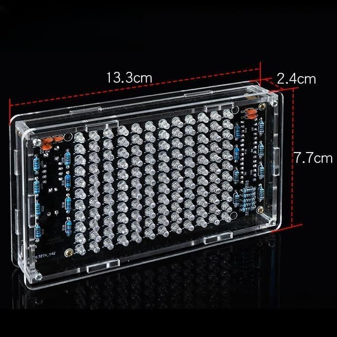
Image: Diagram illustrating the physical dimensions of the assembled MUXWELL Music Spectrum LED Light Kit, showing a length of 13.3 cm, a height of 7.7 cm, and a depth of 2.4 cm.

Image: Detailed circuit diagram for the MUXWELL Music Spectrum LED Light Kit, providing a schematic view of component interconnections, power supply, and LED matrix layout.
10. Warranty and Support
MUXWELL products are designed for quality and performance. This DIY kit is intended for educational and hobbyist use. Due to the nature of DIY assembly, warranty coverage typically applies to manufacturing defects of individual components prior to assembly. For support regarding missing parts, defective components, or assembly guidance, please contact MUXWELL customer service through your retailer's platform or the contact information provided with your purchase.