
1. Introduction
This manual provides essential information for the safe and efficient operation of your AeternaSol 40A MPPT Solar Charge Controller. Please read this manual thoroughly before installation and use. Keep it for future reference.
2. Product Features
- Advanced MPPT Technology: Maximizes power extraction from solar panels with over 99.9% tracking efficiency and 99% conversion efficiency, improving charging by over 30% compared to PWM controllers.
- Automatic 12V/24V System Recognition: Automatically detects and adapts to 12V or 24V battery systems.
- Multi-Battery Compatibility: Supports LiFePO4, Lithium, AGM, GEL, and Flooded battery types.
- Comprehensive Protection: Includes over-voltage, short-circuit, reverse polarity, low-temperature, over-temperature, over-discharge, over-load, and input power limit protection.
- LCD Display & Dual USB Ports: Provides real-time system monitoring and offers two USB ports for charging external devices.
- Rugged Design with Dual Cooling: Features a durable metal casing and intelligent dual-fan design for superior heat dissipation and extended lifespan.
- Three-Stage Charging: Utilizes bulk charge, float charge, and equalization charge for optimized battery health and longevity.
3. Product Overview
Familiarize yourself with the components and interfaces of the AeternaSol 40A MPPT Solar Charge Controller.

Figure 3.1: Product Function Introduction. This image labels the cooling fan, LCD display, Enter button, Up button, Down button, Menu button, Temperature interface, Solar Panel input, Battery terminals, DC Load output, and USB ports.

Figure 3.2: High-End Smart LED Digital Display. This image details the LCD screen showing charging indication, battery percentage, discharge indication, load indication, PV input, battery voltage, load timing indication, fault indication, battery type, and system voltage. It also labels the ESC, Up, Down, and SET buttons.

Figure 3.3: LCD Display, Advanced Cooling System, Parameter Setting Stage, and Large Cross-Section Wiring Port. This image highlights the clarity of the LCD, the pure aluminum heat sink and dual-fan design, the steps for parameter setting (Press ESC, adjust with buttons, Press SET), and the robust wiring ports.
4. Safety Information
Observe the following safety precautions to prevent injury and damage to the controller or other components.
- Explosion Risk: Never install the controller and unsealed batteries in the same enclosed space. Battery gases can accumulate and pose an explosion hazard.
- High Voltage Danger: Photovoltaic arrays can produce high open-circuit voltage. Disconnect the circuit breaker or fuse before wiring and exercise caution during the process.
- Installation Location: Install the controller in a well-ventilated area, away from direct sunlight and high temperatures. Ensure at least 150mm of space above and below the controller for proper cooling.
- Wiring: Always connect the battery first, then the solar panel, and finally the load. Ensure correct polarity for all connections.
- Protection Features: The controller includes built-in protections against low temperature, over-temperature, over-voltage, over-discharge, short-circuit, reverse connection, over-load, and input power limit.

Figure 4.1: 8 Point Safety System. This image visually represents the various protection mechanisms: Low temperature protection, over-temperature protection, over-voltage protection, over-discharge protection, short-circuit protection, reverse-connection protection, over-load protection, and input power limit protection.
5. Setup and Installation
Follow these steps for proper installation of your solar charge controller.
- Choose Installation Location: Select a dry, well-ventilated area, protected from direct sunlight and high temperatures. Ensure adequate clearance (at least 150mm) around the controller for heat dissipation.
- Fix the Controller: Mark the installation position, drill appropriate holes, and securely mount the controller using screws.
- Connect the Battery: Connect the battery to the controller's battery terminals. Ensure correct polarity (positive to positive, negative to negative).
- Connect the Solar Panel: Connect the solar panel array to the controller's solar panel input terminals. Verify correct polarity.
- Connect the DC Load (Optional): If using a DC load directly from the controller, connect it to the DC load output terminals.
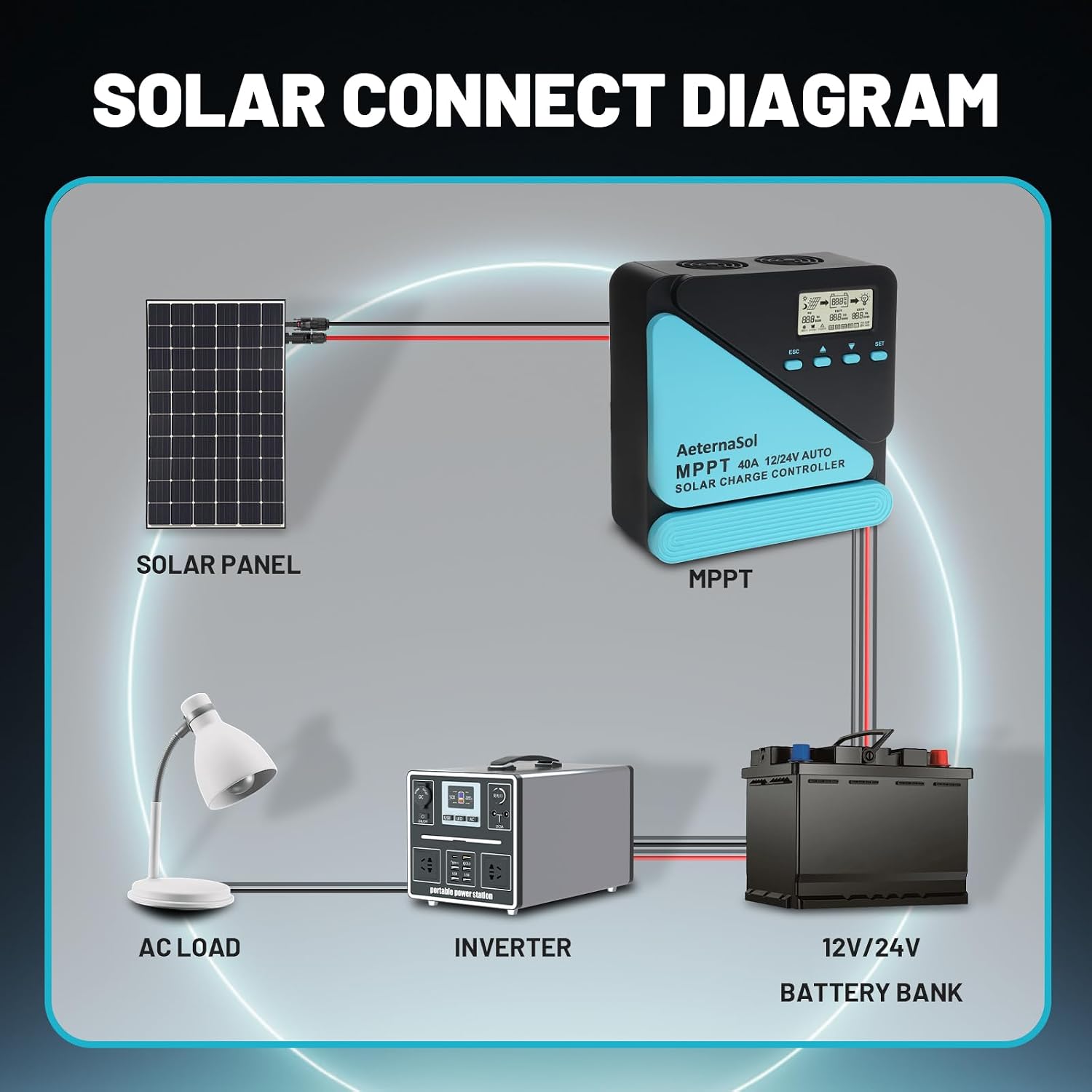
Figure 5.1: Solar Connect Diagram. This diagram illustrates the correct wiring order: Solar Panel to MPPT controller, MPPT controller to 12V/24V Battery Bank, and Battery Bank to Inverter for AC loads.

Figure 5.2: Easy to Connect Diagram. This image provides a simplified visual guide for connecting solar panels, the charge controller, a battery, and an inverter.
Video 5.1: Official AeternaSol video demonstrating the connection process for the solar charge controller. This video shows how to connect the battery, solar panel, and load to the controller.
Video 5.2: Official AeternaSol video providing an overview of the solar charge controller and its features. This video highlights the controller's design and functionality.
6. Operating Instructions
The controller features an intuitive LCD display and buttons for monitoring and setting parameters.
6.1. Parameter Setting
To adjust parameters:
- Press the "ESC" button until the desired value flashes on the LCD.
- Use the "Up" or "Down" buttons to adjust the value.
- Press the "SET" button to confirm and save the changes. The settings will auto-exit after 10 seconds of inactivity.

Figure 6.1: Restore Factory Default and Parameter Setting Stage. This image explains that pressing "ESC" and "SET" for 5 seconds from the main screen restores factory defaults. It also reiterates the steps for parameter setting: Press ESC until value flashes, use buttons to adjust, press SET to confirm and save.
6.2. Battery Type Setting
To select your battery type:
- Press the "ESC" button and navigate to "Battery Type" until the value flashes.
- Use the "Up" or "Down" buttons to select the desired battery type (e.g., LiFePO4, Lithium, AGM, GEL, Flooded).
- Press the "SET" button to confirm and save. The settings will auto-exit after 10 seconds of inactivity.

Figure 6.2: Battery Type Setting. This image illustrates the steps to set the battery type: Press ESC to navigate to battery type, use Up/Down buttons to select, and press SET to confirm.
6.3. Charging Parameter Settings
To adjust charging parameters:
- Press the "ESC" button and navigate to "Charging Parameters" until the value flashes.
- Use the "Up" or "Down" buttons to select the desired parameters.
- Press the "SET" button to confirm and save. The settings will auto-exit after 10 seconds of inactivity.
Attention: Charging parameters cannot be set for FLD (Flooded) and GEL battery types.
6.4. System Voltage Setting
To set the system voltage (12V or 24V):
- Press the "ESC" button and set the voltage type column to "12V 24V" until the value flashes.
- Use the "Up" or "Down" buttons to select the desired voltage.
- Press the "SET" button to confirm and save. The settings will auto-exit after 10 seconds of inactivity.
6.5. Load Working Modes
The controller supports three load working modes:
- (1H-23H) Lighting Time Control Mode: Automatically turns the load on or off according to the intensity of sunlight and a set timer.
- (0H) Normal OFF Mode: The load remains off. This mode is used for special loads or debugging.
- (24H) Normal ON Mode: The load remains continuously on. This mode is suitable for loads that require a 24-hour power supply.

Figure 6.3: Application Scenarios. This image displays the controller being used in an RV, a cabin, a camping setup, and a home solar energy system, demonstrating its versatility.
7. Maintenance
Regular maintenance ensures optimal performance and longevity of your solar charge controller.
- Inspect Connections: Periodically check all wiring connections for tightness and corrosion. Loose connections can cause overheating and poor performance.
- Clean the Controller: Keep the controller clean and free from dust and debris. Use a dry cloth to wipe the exterior. Ensure cooling vents are unobstructed.
- Monitor Performance: Regularly check the LCD display for system status, battery voltage, and charging current to ensure normal operation.
- Battery Health: Monitor battery health and ensure it is compatible with the controller's settings.
- Cooling Fan: The intelligent dual-fan design helps maintain optimal operating temperature. Ensure the fan is not blocked and is functioning correctly.

Figure 7.1: Cooling Fan. This image emphasizes the importance of the cooling fan in reducing the controller's temperature during charging to extend its lifespan.

Figure 7.2: Dual Cooling, Efficient Heat Dissipation. This image shows the specially designed metal heat sinks and intelligent dual-fan design that ensure efficient heat dissipation and reduce power consumption.
8. Troubleshooting
If you encounter issues with your AeternaSol 40A MPPT Solar Charge Controller, refer to the following common problems and solutions.
| Problem | Possible Cause | Solution |
|---|---|---|
| No display on LCD | Battery not connected or low voltage; reverse polarity connection. | Check battery connections and voltage. Ensure correct polarity. Charge battery if voltage is too low. |
| No charging from solar panel | Solar panel not connected; low solar input; reverse polarity; faulty panel. | Verify solar panel connections and polarity. Check for sufficient sunlight. Test solar panel output. |
| Load not working | Load not connected; load working mode incorrect; over-load protection activated. | Check load connections. Verify load working mode settings. Reduce load or check for short circuits. |
| Controller overheating | Poor ventilation; excessive load; high ambient temperature. | Ensure adequate clearance around the controller. Reduce load. Relocate to a cooler area if possible. |
If the problem persists after attempting these solutions, please contact AeternaSol customer support.
9. Specifications
Key technical specifications for the AeternaSol 40A MPPT Solar Charge Controller.
| Feature | Specification |
|---|---|
| Model | ASL40 |
| Rated Charging Current | 40A |
| System Voltage | 12V/24V Auto Recognition |
| Max. PV Input Voltage | 100V |
| Max. PV Input Power (12V System) | 480W |
| Max. PV Input Power (24V System) | 960W |
| Tracking Efficiency | 99.5% |
| Conversion Efficiency | 99% |
| Battery Types Supported | LiFePO4, Lithium, AGM, GEL, Flooded |
| Display Type | LCD |
| USB Output | Dual USB Ports |
| Product Dimensions (L x W x H) | 8.5" x 3.5" x 7.5" |
| Material | Acrylonitrile Butadiene Styrene (ABS) |
| Weight | 2.5 pounds |

Figure 9.1: Max PV Input Power and Voltage Table. This table provides detailed specifications for maximum PV input power and voltage for 12V and 24V systems, categorized by controller current ratings (20A, 30A, 40A, 60A).
10. Warranty and Support
AeternaSol products are designed for reliability and performance. For warranty information and customer support, please refer to the official AeternaSol website or contact your retailer.
- Warranty: Please retain your proof of purchase for warranty claims.
- Customer Support: For technical assistance, troubleshooting, or service inquiries, please visit the AeternaSol Store on Amazon or contact AeternaSol Direct.