
1. Product Overview
The VTSYIQI 4-Wire Earth Ground Resistance Tester is a precision instrument designed for measuring grounding resistance and soil resistivity. It utilizes advanced microprocessor technology and a large LCD gray-white screen with backlight for clear display. This tester supports two-wire, three-wire, and four-wire test methods, making it versatile for various applications.
It is suitable for use in telecommunications, electricity, meteorology, computer rooms, oil fields, power distribution lines, iron tower transmission lines, gas stations, factory grounding networks, and lightning rod installations. The instrument provides precise, fast, simple, stable, and reliable measurements.

Image 1.1: The VTSYIQI 4-Wire Earth Ground Resistance Tester, showcasing its robust design and clear display.
2. Safety Information
Always adhere to local safety regulations and guidelines when operating this instrument. Ensure proper grounding connections are made before initiating any tests. Do not operate the device in wet conditions or in the presence of flammable gases or vapors. Disconnect all test leads before opening the battery compartment or performing any maintenance. Only use accessories and replacement parts specified by the manufacturer.
3. Package Contents
Verify that all items listed below are present and in good condition upon unpacking:
- Main Host Unit (Earth Ground Resistance Tester)
- Test Lines (various colors for H, S, ES, E connections)
- Auxiliary Ground Rods (4 pieces)
- USB Cable
- Monitoring Software CD
- Power Adapter
- User Manual

Image 3.1: All components included with the VTSYIQI Earth Ground Resistance Tester, including the main unit, test leads, ground rods, USB cable, software CD, and power adapter.
4. Product Features
- Measurement Capabilities: Measures grounding resistance, soil resistivity, ground voltage, and AC voltage.
- Test Methods: Supports precise four-wire, three-wire, and simple two-wire measurements.
- Microprocessor Control: Automatically detects connection status, interference voltage, and frequency.
- Data Storage: Stores up to 500 sets of measurement data.
- USB Interface: Allows online monitoring and data upload to a PC via monitoring software.
- Intelligent Alarm: Features intelligent alarm alerts for out-of-range conditions.
- Large LCD Display: Gray-white screen with backlight for clear readability.
5. Specifications
| Parameter | Value |
|---|---|
| Grounding Resistance Range | 0.00Ω ~ 30.00kΩ |
| Soil Resistivity Range | 0.00Ωm ~ 9999kΩm |
| Grounding Voltage Range | 0.00V ~ 100.0V |
| Power Source | 8.4V Lithium Battery (built-in) |
| Interference Voltage Limit | < 20V (should be avoided) |
| Interference Current Limit | < 2A (should be avoided) |
| Ambient Temperature | 23℃ ± 5℃ |
| Relative Humidity | Below 75% RH |
| Data Storage | 500 groups |
| Interface | USB |
| Dimensions (L x W x H) | 17.72 x 5.91 x 9.84 inches |
6. Setup and Connection
Proper setup is crucial for accurate measurements. Follow these steps for a typical 4-wire soil resistivity test:
- Prepare the Test Site: Select a suitable area for testing. Ensure the ground is relatively flat and free from obstructions.
- Install Ground Piles: Drive the four auxiliary ground rods into the earth in a straight line, maintaining equal spacing (a) between them. The depth (d) of the rods should be less than 1/20th of the spacing (a > 20h, where h is the depth). Ensure the spacing between the R electrode and the measured electrode is a > 5d.
- Connect Test Leads: Connect the four color-coded test leads from the instrument to the ground rods. Typically, the connections are as follows:
- Red lead to H (Current Electrode)
- Yellow lead to S (Potential Electrode)
- Green lead to ES (Auxiliary Potential Electrode)
- Black lead to E (Auxiliary Current Electrode)
- Power On: Open the instrument lid and connect the test leads to the corresponding terminals on the tester. Press the power button to turn on the device.

Image 6.1: Diagram illustrating the 4-wire precision test ground resistance setup, showing the placement of ground rods and connections to the tester.
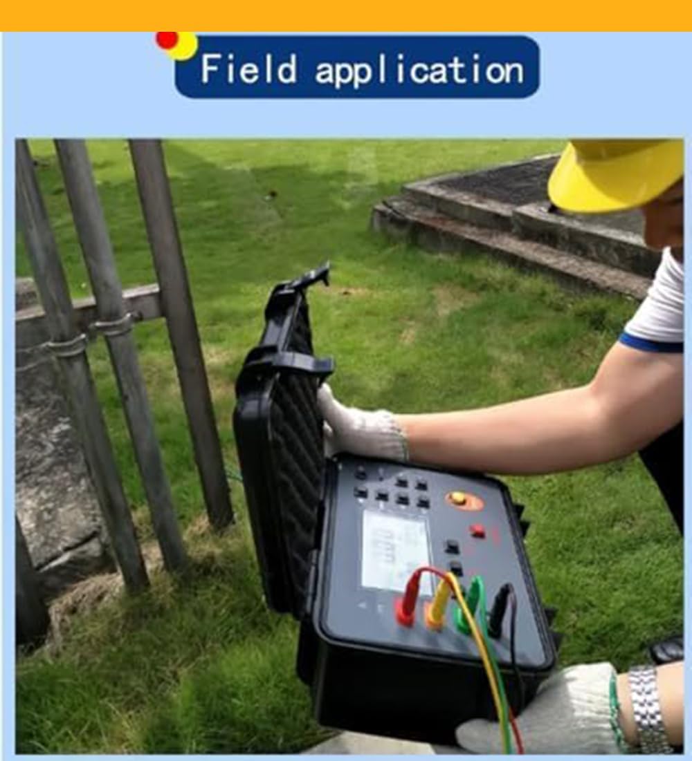
Image 6.2: A user setting up the VTSYIQI Earth Ground Resistance Tester in a field environment, demonstrating the practical application of the device.
7. Operating Instructions
Once the setup is complete, proceed with the measurement:
- Select Test Mode: On the instrument's control panel, press the appropriate button to select the desired test mode (e.g., soil resistivity test).
- Initiate Test: Press the 'TEST' button to begin the measurement. The green light will start flashing, indicating the test is in progress.
- Wait for Countdown: The instrument will display a countdown. Wait for the countdown to complete.
- Read Results: After the countdown, the measured soil resistivity value will be displayed on the screen. For example, a reading of 70.62 Ωm indicates the soil resistivity.
- Save Data: Use the data storage functions to save the measurement results if needed.
Video 7.1: Demonstration of a 4-wire soil resistance test using the VTSYIQI Earth Ground Resistance Tester. The video shows the process from ground piling and lead connection to initiating the test and displaying the final resistivity measurement.

Image 7.2: A close-up view of the tester's LCD display, showing the measured resistance (R) and soil resistivity (RH, RS) values.
8. Maintenance
- Cleaning: Wipe the instrument with a soft, dry cloth. Do not use abrasive cleaners or solvents.
- Storage: Store the tester in its protective case in a cool, dry place away from direct sunlight and extreme temperatures.
- Battery: Ensure the built-in lithium battery is charged regularly, especially if the instrument is not used for extended periods.
- Calibration: Regular calibration by qualified personnel is recommended to maintain measurement accuracy.
- Software: Keep the monitoring software updated to ensure compatibility and optimal performance.
9. Troubleshooting
If you encounter issues with the instrument, refer to the following common problems and solutions:
| Problem | Possible Cause | Solution |
|---|---|---|
| No display after power on | Low battery or power issue | Charge the battery or check power adapter connection. |
| Inaccurate readings | Poor lead connections, high interference, incorrect setup | Ensure all leads are securely connected. Re-evaluate ground rod placement and spacing. Test in an area with less electrical interference. |
| "OVER" or "OL" displayed | Measurement range exceeded or open circuit | Check for broken test leads or poor contact with ground rods. Ensure the resistance is within the instrument's measurable range. |
| Data transfer issues via USB | Driver not installed, faulty USB cable, software incompatibility | Install the provided monitoring software and drivers. Try a different USB cable. Ensure the software is compatible with your operating system. |
10. Warranty and Support
For warranty information and technical support, please refer to the documentation provided with your purchase or contact VTSYIQI customer service directly. Keep your purchase receipt as proof of purchase for warranty claims.