1. Introduction
The WEQRTXG LCR-TC2 is a versatile multifunction transistor tester featuring a TFT graphic display. It is designed for automatic detection and measurement of various electronic components, including NPN and PNP bipolar transistors, N-channel and P-channel MOSFETs, JFETs, diodes (including double diodes), N- and P-IGBTs, resistors, capacitors, inductors, thyristors, triacs, and Zener diodes. It also includes an IR decoder function.
2. Safety Precautions
- Warning: Always discharge capacitors before connecting them to the tester. Failure to do so may damage the tester.
- Warning: Do not test components or circuits that are powered or live. Testing with electricity can burn out the tester.
- Warning: Do not hook the three test hooks onto a live circuit board for testing.
- Warning: The instrument provides active output. Do not use the test lines to test charged circuit boards, as this can easily damage the instrument.
- Warning: For your personal safety, strictly observe all specifications and precautions for using lithium-ion batteries. The built-in lithium-ion battery must not be immersed in water or placed near heat sources.
- Warning: If the internal battery voltage is below 3V, please charge the device before use. Use a 5V power source or USB port for charging.
- Warning: We do not recommend using the tester to measure batteries. If you must, ensure the battery voltage is less than 4.5V; otherwise, the tester may be damaged.
- Caution: Do not perform other operations during the calibration process to avoid affecting calibration accuracy.
3. Package Contents
Verify that all items are present in your package:
- 1 x WEQRTXG LCR-TC2 Multifunction TFT Transistor Tester
- 1 x Electronic Component Group (random assortment)
- 3 x Test Hooks
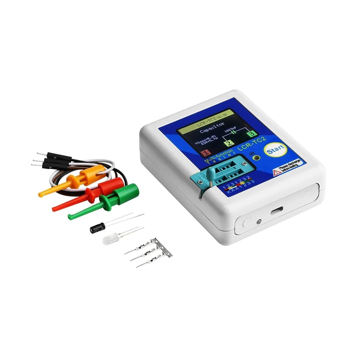
Image: The LCR-TC2 tester shown with its accompanying accessories, including test hooks, a USB charging cable, and a small assortment of electronic components for testing.
4. Setup
4.1 Charging the Device
The LCR-TC2 has a built-in rechargeable lithium-ion battery. If the battery voltage drops below 3V, the device will indicate a low battery. Connect the tester to a 5V USB power source using the provided Micro USB cable to charge it.
4.2 Power On
In the power-off state, perform a short press on the multi-function key. The tester will turn on and automatically initiate a measurement cycle.
Image: A clear view of the LCR-TC2's front panel, highlighting the TFT color display, the 'Start' multi-function button, and the component test socket.
5. Operating Instructions
5.1 Key Operational Definitions
- Short Press: Press the multi-function key for at least 10 milliseconds and release it within 1.5 seconds.
- Long Press: Press and hold the multi-function key for more than 1.5 seconds.
5.2 Component Placement
The test socket on the LCR-TC2 is designed with a transistor test area and a Zener diode test area. Ensure components are placed correctly for accurate readings.

Image: The LCR-TC2 tester with its test hooks connected to the component test socket, demonstrating how to interface components for measurement.
5.3 Transistor and General Component Detection
After ensuring the component is discharged and the tester is powered on:
- Place the component into the transistor test area of the test socket. The socket is labeled with pin numbers (1, 2, 3) and a KAA area.
- Press the lock handle to secure the component.
- Press the multi-function key (short press).
- The tester will automatically measure the component and display the results on the TFT screen, including component type, pin layout, and measured parameters.
For accurate measurements, use the three test hooks to connect directly to the component if possible, especially for capacitors.
5.4 Zener Diode Detection
The LCR-TC2 can automatically detect Zener diodes within a range of 0.01V to 30V. Place the Zener diode in the designated test area or the general component test area, and the tester will identify and measure it.
5.5 IR Decoder Function
The tester includes an IR receiver window. It supports IR coding, can display IR waveforms, and provides infrared receiving instructions. Point an IR remote control towards the IR receiver window and press a button to observe the IR signal.
6. Calibration
The LCR-TC2 features a self-test with automatic calibration for improved accuracy.
- Short circuit the three test sockets (pins 1, 2, and 3).
- Perform a short press on the multi-function button.
- The tester will automatically begin the calibration process.
- Follow any on-screen prompts. Once prompted, disconnect the short wiring.
- No other operations are required during the calibration process to ensure accuracy.
7. Specifications
| Feature | Specification |
|---|---|
| Model | LCR-TC2 |
| Display | TFT Color Screen (160x128 resolution) |
| Dimensions | Approx. 70 x 90 x 26 mm (2.71 x 3.58 x 1.10 inches) |
| Power Source | Built-in Rechargeable Lithium Battery (3.7V) |
| Diode Range | Less than 4.5V |
| Zener Diode Detect Area | 0.01V - 30V |
| Triac Range | IGT less than 6mA |
| Capacitance Range | 25pF - 100mF |
| Resistor Range | 0.01Ω - 50MΩ |
| Inductance Range | 0.01mH - 20H |
| Auto Power Off | Yes (timeout settable) |
| Language Support | Chinese and English |
8. Troubleshooting
- Tester does not power on: Ensure the battery is charged. Connect to a 5V USB power source.
- Inaccurate readings: Perform a calibration as described in Section 6. Ensure components are properly discharged before testing.
- Tester burnt out: This typically occurs from testing live circuits or charged capacitors without discharge. Always follow safety precautions.
- Display shows 'Unknown or Damaged Part': The component might be faulty, or it's a type not supported by the tester. Ensure proper placement in the test socket.
9. Warranty and Support
For warranty information or technical support, please refer to the seller's policies or contact the manufacturer directly. Keep your purchase receipt for any warranty claims.


